HL7 V3 Guide
Last Published: 09/29/2005 10:16 PM
HL7® Version 3 Standard, © 2005 Health Level Sevens®, Inc. All Rights Reserved.
HL7 and Health Level Seven are registered trademarks of Health Level Seven, Inc. Reg. U.S. Pat & TM Off
Table of Contents
Appendices
1
Foreword
HL7 as an organization, is re-orienting itself to become even more responsive to its members interests. Since speed to market is of interest to many HL7 members, whether they are vendors or providers that implement the specifications, being more nimble is highly desirable.
This means that HL7 may take on a task of developing specifications in an emerging messaging area where there are few actual implementations in place. HL7 specifications become enablers of business processes that don't yet exist. In many cases, consensus emerges to meet part of the requirements, but not yet all of the requirements.
In other cases, the timing and workload of various Technical Committees is such that only some of the Technical Committees have had the opportunity to propose specifications that may eventually be considered valuable by other Technical Committees. In still other cases, a partial specification may be published in a ballot to solicit feedback from a wider audience on the practicality of the proposed solution.
Managing the workload of the entire membership, across the many Technical Committees working in parallel, is always a challenge. When a specification release is due, specifications that are ready for a wider audience are assembled and published. The intent is not only to provide specifications for implementation, but in some cases, to provide specifications that are the foundations for work-in-progress that will more fully emerge in future versions. Early feedback from broader audiences and support for early adopters will improve the quality of all the specifications produced by HL7.
HL7 is beginning to use the best practices of successful development groups, whether the product is software or specifications. We are producing products in managed releases, using models during development to manage complexity and support coherence, using automation during the development process to improve productivity and quality, encouraging cross-organization communication, getting early feedback from our client community and being responsive to our clients' needs.
1.1
About This Guide
This HL7 V3 Guide was created for use by members of the Health Level Seven (HL7) Working Group as a companion to the V3 Standard. An earlier document the Message Development Framework contained additional supporting design and architecture material for V3. However the MDF has not been maintained in alignment with current V3 ballots and is therefore not recommended for use. A new document the HDF, HL7 Development Framework will in time provide the replacement for the MDF. However it contains changes to the UML notations and approach which vary from this Ballot and in any case is still in draft form. Refer also to the Glossary to clarify meaning of terms used in this document.
The V3 Guide is divided into two sections, FOUNDATION COMPONENTS and MESSAGING COMPONENTS. The FOUNDATION COMPONENTS section consists of chapters about information models, vocabulary, data types, and the Implementation Technology Specification (ITS), as used within the HL7 Version 3 specifications. The MESSAGING COMPONENTS section provides guidance on the artifacts found in the Version 3 standard, such as storyboards, trigger events, interactions, etc., and is intended to help the reader understand how to read and use these artifacts. Readers of the V3 Guide will need a general understanding of both the foundation and messaging components to understand the V3 Specifications themselves.
2
HL7 Foundation Components
2.1
Introduction
The Version 3 publication consists of several documents. Some of these documents contain the V3 specifications themselves while others contain information that is crucial to the development or transport of HL7 messages. The foundation component documents fall into the latter category and are illustrated in the figure below:
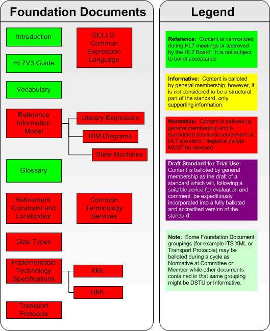
A general understanding of the foundation components discussed in this section is needed to appreciate the messaging components discussed in the MESSAGING COMPONENTS section of the V3 Guide. The foundation components include:
- Information Model - Describes the types of information models in HL7's Version 3 standard, including the Reference Information Model (RIM).
- Vocabulary - Discusses the use of controlled vocabulary within the HL7 V3 Specifications and the HL7 Vocabulary Technical Committee's principles and approach to vocabulary use and management.
- Implementation Technology Specification (ITS) - Describes the Implementation Technology Specification document and its function.
- Data Types - Describes the underlying principles of the V3 data types.
- Common Message Element Types (CMETs) - Describes the purpose, definition, and use of CMETs.
- Examples - Shows an example of a V2.4 message and an equivalent V3 representation of that same message using the XML ITS (including mapping notes).
2.2
Information Model
An information model is a structured specification of the information within a specific domain of interest. It expresses the classes of information required and the properties of those classes, including attributes, relationships, constraints, and states. In HL7, the scope of a domain of interest ranges from the domain of the entire system of health services to the specific context of a set of information exchanges to meet a particular identified business purpose. HL7 defines different types of information models to represent the different contexts of interest.
2.2.1
Information Model Components
The information model consists of the following components:
classes, their attributes, and relationships between the classes;
data types for all attributes and vocabulary domains for coded attributes;
state transition models for some classes.
HL7 information models are based upon the Unified Modeling Language (UML), and may be represented graphically using the UML style. UML is a modeling language that unifies the object-oriented modeling methods of Grady Booch, Jim Rumbaugh, Ivar Jacobson, and others. The UML is a rich, mainly graphical, means of expressing object-oriented concepts. To obtain more information about UML see http://www.rational.com/uml/ or the book UML Distilled by Martin Fowler (ISBN 0-201-32563-2).
2.2.2
Types of Information Models
The HL7 information modeling process recognizes three interrelated types of information models. Each of the model types uses the same notation and has the same basic structure. The models differ from each other based on their information content, scope, and intended use. The following types of information models are defined:
- Reference Information Model (RIM)- The RIM is used to express the information content for the collective work of the HL7 Working Group. It is the information model that encompasses the HL7 domain of interest as a whole. The RIM is a coherent, shared information model that is the source for the data content of all HL7 messages. As such, it provides consistent data and concept reuse across multiple information structures, including messages. The RIM is maintained by a collaborative, consensus building process involving all Technical Committees and Special Interest Groups. This process, known as model harmonization, uses standard consensus processes, to review, debate, enhance, and reconcile change proposals that have been submitted by Technical Committees. The resulting changes are applied to the RIM to produce a new version. The RIM is intentionally abstract allowing it to represent the richness of the information topics that must be shared throughout the health system. The principles underlying this abstraction are discussed in detail in the introduction to the RIM.
- Domain Message Information Model (D-MIM)- A D-MIM is a refined subset of the RIM that includes a set of class clones, attributes and relationships that can be used to create messages for a particular domain (a particular area of interest in healthcare). The D-MIM is used as a common base upon which all R-MIMs within a domain are built. The rules for the refinement process by which the D-MIMs and R-MIMs are created are discussed in detail in the specification on Refinement and Localization.
- Refined Message Information Model (R-MIM)- The R-MIM is a subset of a D-MIM that is used to express the information content for a message or set of messages with annotations and refinements that are message specific. The content of an R-MIM is drawn from the D-MIM for the specific domain in which the R-MIM is used. The R-MIM may include clones of selected classes with alias names specific to the perspective of the message(s) to be derived. The R-MIM represents the information content for one or more abstract message structures, also called Hierarchal Message Definitions (HMDs).
2.2.3
Static Structure: Classes and Relationships
2.2.3.1
Classes
A class is an abstraction of things or concepts that are subjects of interest in a given application domain. All things or concepts subsumed under a class have the same properties and are subject to and conform to the same rules. Classes are the people, places, roles, things, and events about which information is kept. Classes have a name, description, and sets of attributes, relationships, and states.
The instances of classes are called objects. Where classes represent categories of concepts, people and things, objects represent the individual things themselves. There is still a difference between objects and the things they represent. Objects capture all relevant data about things that are known to the information system, but are not the things themselves. For instance, a particular human being, named John Doe, may be represented through an object in an information system. That object contains John Doe's demographic or medical data, but the object is still different from John Doe himself.
2.2.3.2
Relationships
Classes relate to other classes in various ways. Such relationships are of two types: Generalization and Association. These are discussed in more detail below.
Generalizations
A generalization relationship is a connection between classes (as opposed to objects). It is an association between two classes (a superclass and a subclass) in which the subclass is derived from the superclass (i.e., the superclass generalizes the subclass and the subclass is a specialization of the superclass). The subclass inherits all properties from the superclass, including attributes, relationships, and states. Instances of a subclass are also instances of the superclass.
In a generalization relationship the subclass inherits all properties from the superclass, including attributes, relationships, and states. In addition, the subclass has other properties that are special for the subclass.
Each subclass may in turn have subclasses of its own. Thus, superclass/subclass and generalization/specialization are relative concepts. A class can be both a subclass of its superclass and a superclass of its subclasses. The entirety of superclasses and subclasses with a common root superclass is called a generalization hierarchy.
A generalization usually has multiple specializations. However, not all of the conceptual specializations need to be represented in the model. Only those concepts that warrant special properties (e.g., attributes, relationships, states) are modeled as distinguished classes. If all specializations of a class are fully enumerated as subclasses in the model, the superclass could be "abstract." An abstract class is never instantiated directly, but only through one of its specializations.
Associations
An association defines a relationship between objects. The objects may be instances of two different classes or of the same class (reflexive association). Just as classes have instances, associations have instances too. An association instance is a connection between objects and is defined by an association that connects classes.
Associations in the HL7 information models have at least two ends. Each end of the association instance connects with one and only one object. However, one object may be associated with more than one object of the same class by the same association. In this case, multiple association instances exist, each connecting exactly two objects. The number of instances of an association that can connect to one object is regulated by the multiplicities of the association.
An association multiplicity specifies the minimum and maximum number of objects of each class participating in the association. The multiplicity is expressed as a pair of cardinal numbers (i.e., non-negative integers) min..max. The lower bound min is a non-negative integer, usually zero or one. The upper bound max is an integer greater or equal to min, usually one, or unlimited, indicated by an asterisk ("*").1 Valid multiplicities are listed in the following table:
| Multiplicity | Meaning |
|---|---|
| 0..1 | minimum zero, maximum one |
| 0..n | minimum zero, maximum the integer n, where n > 1 |
| 0..* | minimum zero, maximum unlimited |
| 1 | short for "1..1" minimum one, maximum one |
| 1..n | minimum one, maximum the integer n, where n > 1 |
| 1..* | minimum one, maximum unlimited |
| n1..n2 | minimum the integer n1, maximum the integer n2, where n1 > 1 and n2 >n1 |
| n..* | minimum the integer n, maximum unlimited, where n > 1 |
2.2.4
Attributes
Class attributes are the core components of the information model. The attributes are the source for all the information content of HL7. The majority of attributes are descriptive attributes that depict aspects of classes that are important for communication between healthcare systems. Besides the descriptive attributes, there are three special kinds of attributes in the information model: identifier attributes, classifier attributes and state attributes. These are discussed in more detail below.
Identifier Attributes
Identifier attributes can be used to identify an instance of a class. Sometimes more than one attribute may be needed to identify an instance of a class. The identifier attributes always have a value. The values of identifier attributes are unique among all instances of the class. Since identity is static, values of identifier attributes never change. Identifier attributes are assigned the “set of instance identifier (SETII) data type and generally have the name "id" that allow for multiple identifiers to be specified.
Examples of identifier attributes from the RIM include Entity.id and Act.id, which uniquely identify a particular Entity or Act respectively. In each case, the identifier attributes are a set of instance identifiers. This indicates that there may be multiple, unique identifiers for an Entity or Act. Entity identifiers might include device serial numbers, social security numbers, driver license numbers, and others. Act identifiers might include placer accession numbers, filler accession numbers, and others.
Classifier Attributes
The classifier attributes are a critical aspect of the classes forming the backbone of the RIM (Entity, Role, and Act). The classifier attributes are named "classCode". The classifier attributes provide a great amount of flexibility and extensibility in the information model. The vocabulary domains for classifier attributes include an entry for each specialization of the backbone class. For example the vocabulary domain specified for Entity.classCode includes living subject, organization, place and material. The vocabulary domain may also include entries that are not explicitly expressed as classes in the model. For example, group is a valid Entity class code (or specialization of Entity) but does not appear in the model as a class. This provides the flexibility and extensibility capability.
Structural Attributes
Structural attributes are those attributes whose coded values are needed to fully interpret the classes that they classify. They are a small set of mandatory attributes, including the classifier attribute: ClassCode described in the previous paragraph, together with moodCode, typeCode and determinerCode. All four are not found in every class. For instance neither Acts or Entities use determinerCode. Exactly as with classCodes there is a bounded vocabulary, managed by HL7 against each use of a structural attribute. For instance, for the mood attribute in Act, there is an actMood vocabulary.
State Attributes
A state attribute is used in subject classes (classes that a Technical Committee designates as the central focus of a collection of messages). It contains a value that concisely indicates the current state (named condition) of the class. A subject class must have only one state attribute. The state attribute must be assigned the data type "set of code value" that allows multiple state flags to be specified. State attributes are named status_cd and are associated with vocabulary domains defined by HL7 that correspond to the state machine defined for the subject class. For example, Act.status_cd has the domain values which include active, suspended, cancelled, completed, and aborted.
2.2.5
Constraints
Constraints narrow the set of possible values that an attribute can take on. Constraints include vocabulary domain constraints (e.g., this attribute must be a LOINC code), range constraints (e.g., this attribute must be a floating point number between 0 and 1) etc. While the term "constraint" has the connotation of restricting and limiting, the objective in defining constraints is more to provide guidance in the proper use of a class or attribute.
Constraints may be specified in the RIM, D-MIM, R-MIM or hierarchical message description (HMD). If specified in the RIM, the constraint is relevant for an attribute in all messages containing the attribute. If specified in the D-MIM or R-MIM, the constraint is specific to all of the messages derived from that D-MIM or R-MIM. Constraints may also be specified within the HMD where they can be made specific to a particular set of message structures. Constraints specified in a higher level (e.g., the RIM) may be further constrained in a lower level (e.g., D-MIM or HMD). However, the subordinate constraint must conform to the constraint on the higher level. Higher level constraints cannot be undone on a lower level. (Constraints are discussed in greater detail in the normative section on Refinement,Constraint and Localization.)
2.2.6
Dynamic Behavior: States and Transitions
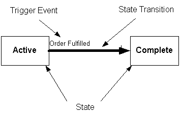
The behavioral aspect of a class is defined in a state diagram associated with a class in an information model. State diagrams, which show all of the potential states for a class, are developed for classes that are the central subject of an interaction. These classes are called subject classes. Interactions are sometimes motivated by changes in the state of a subject class. For example, Act may be identified as a subject class. The vocabulary domain for the Act.status_cd declares the defined states for the Act. Those states include Active, Suspended, Cancelled, Complete, and Aborted. A state diagram depicts the allowable class states with a box labeled with the name of the state. Changes in state are called state transitions and are depicted in the diagram by a line with a arrowhead showing the direction of the transition. An example of a state transition might be the change in the state of an Act from Active to Complete. The change in state (state transition) is associated with a trigger event that causes the transition. The trigger event in this example might be the fulfillment of an order. An order is a special type of Act. The transition from an Active order to a Completed order is triggered by the fulfillment of the Order. The state diagram depicts the states, trigger event, and state transitions of interest.
2.3
Vocabulary
Within HL7, a vocabulary domain is the set of all concepts that can be taken as valid values in an instance of a coded field or attribute. For example, the Living_subject class has a coded attribute called administrative_gender_cd. If the administrative_gender_cd attribute becomes part of an HMD, and a message instance is subsequently created as part of an implemented interface, one would expect the administrative_gender_cd attribute to convey male or female. In this example, male and female are concepts and there may be several coding schemes that contain concepts for male and female.
It is important to note that a vocabulary domain consists of a set of concepts, not a set of words or codes. In different implementations of an interface, the same concept could be represented using different coding systems. Thus, each concept in a vocabulary domain has a one-to-many relationship to codes that might be used as representations for the concept in a message instance.
The general meaning of coding system is a scheme for representing concepts using (usually) short concept identifiers to denote the concepts that are members of the system. A coding scheme defines a set of unique concept codes.
2.3.1
Vocabulary Domains and RIM Attributes
Each coded attribute in the RIM (i.e., with a data type of CD, CE, CR, CS or CV ) will be associated with one and only one vocabulary domain. For example the vocabulary domain for administrative_gender_cd is AdmistrativeGender. Some vocabulary domains are associated with more than one RIM attribute. For example the Vocabulary domain PhysicalQuantity is associated with both diet_carbohydrate_qty and Diet_energy_qty. The vocabulary domain table may be an HL7-defined table, an HL7-recognized external coding scheme (e.g., LOINC, SNOMED) or some combination of those. It may contain locally-defined codes.
The HL7-defined vocabulary domain tables that have been developed for coded class attributes are stored in the HL7 repository. A number of printable views have been extracted to produce the HL7 Vocabulary Domain listings. The views are presented in table format and include the HL7 Vocabulary Domain Values list and the HL7 Domain Tables and Coded Attributes list. HL7-recognized external vocabulary domains are described in the External Domains list. Links are provided between these tables and attributes in the RIM.
The HL7 Vocabulary Domain Values table includes a mnemonic code, concept identifier, print name, and definition/description for each value. This table also shows any hierarchical relationship that exists between values in each domain table.
The HL7 Domain Tables and the Coded Attributes table name the coded attribute(s) in the RIM that are supported by that vocabulary domain.
The External Domains table includes Concept Identifier, Defining Expression, Code System Abbreviation, Description, and a link to the source for each table.
2.3.2
Vocabulary Domain Qualifiers
Coded fields contain two pieces of information relative to Vocabulary: the Vocabulary Domain name and the Extensibility Qualifier. The Extensibility Qualifier has two possible values: CNE (coded no extensions), and CWE (coded with extensions).
The vocabulary domain name and the associated Extensibility qualifier for each coded attribute in the RIM are specified in the RIM narrative. This specification occurs as the first line of the description for a coded RIM class attribute. The information is formatted as shown in the example below from Entity.class_cd:
Domain: "EntityClass" (CNE)
There is a hyperlink between the Vocabulary Domain name (EntityClass) and its entry in the HL7 Vocabulary Domain Values table. For those domains that are not yet developed, a domain name has been assigned but the table contains no values.
The CWE value for the Extensibility qualifier means that the code set can be expanded to meet local implementation needs. When a coded attribute is sent in a message, local concepts or free text may be sent in place of a standard code if the desired concept is not represented in the standard vocabulary domain.
The CNE value for the Extensibility qualifier means that the code set is fixed and cannot be extended. A concept from the specified domain must be sent as the value of the coded field in a message. If the field cannot be valued from the concepts that exist in the specified domain, the field cannot be placed in the message. If a CNE field is required in a message, but the field cannot be valued from the concepts that exist in the specified domain, then no valid message can be created.
The Realm qualifier allows the domain of a coded attribute to be specialized according to the geographical, organizational, or political environment where the HL7 standard is being used. For example, the Realm qualifier would allow the Gender domain to hold a somewhat different value set for HL7 messages when used in Japan versus when the Gender domain is used in HL7 messages in the United States.
All domain qualifiers are values in the VocabularyDomainQualifier domain.
2.3.3
Use of Vocabulary Constraints
Constraints are applied to RIM classes and their coded RIM attributes by selecting appropriate values from the vocabulary domains for those attributes.
The vocabulary domain specifications stated in the RIM always refer to a complete vocabulary domain. That is, at the RIM level there is no specialization based on Realm of use or on the context and needs of a specific message. As RIM attributes are specialized to suit a specific message context, the domain of the attribute can be reduced (constrained) to reflect the specialization.
A domain that has been constrained to a particular Realm and coding system is called a value set. A vocabulary domain constraint can be applied to any level below the RIM, and is an expression that states how the value set was derived from the domain specified in the RIM. A vocabulary domain constraint in an R-MIM, D-MIM, etc. contains the name of the value set and its list of domain qualifiers. Domain constraint expressions are only contained in the Value Set Definition Table.
The general rule for creating vocabulary domain constraints is that a domain can be reduced in scope as it is specialized for a particular use, but its semantic scope can never be expanded. The application of the general rule results in the following specific rules.
The vocabulary domain of a coded element or attribute used at any level of specialization below the RIM must be a subset of the vocabulary domain specified for the attribute in the RIM. Note that for attributes that are qualified with an extensibility of CWE, local codes are an allowed extension to the domain, but this is not intended as an increase in the semantic scope of the attribute.
Once the extensibility qualifier value CNE has been invoked at any level of attribute domain specification (RIM, D-MIM, R-MIM, CMET, HMD, etc.,), the CNE qualifier must be retained in any subsequent domain constraints. For example, if a coded attribute has a CNE qualifier in the RIM, any D-MIM, R-MIM, CMET, HMD, etc must also have a CNE qualifier associated with the domain of that attribute. If a vocabulary domain in the RIM has the Extensibility qualifier value of CWE (coded with extensions), a subsequent constraint of that attribute's domain can have either the CNE or CWE qualifier.
2.4
Implementation Technology Specifications
The Implementation Technology Specification, or ITS, defines how to represent RIM objects for transmission in messages. It covers ISO levels 6 and 5. HL7 has adopted XML for its initially balloted ITS.The Guide text summarises the XML ITS. A UML ITS has recently been developed and is part of current ballots.
HL7 defines its messages at an abstract level. The "7" in HL7 stands for the Application level of the ISO communication model -- ISO level 7. This level emphasizes the semantic content of the messages, not how they are represented, nor how these representations are encoded for transmission.
The HL7 Version 2 abstract message model has the notions of segments and fields. It defines a particular encoding scheme to represent instances of abstract messages -- the so called "vertical bar encoding." Information from the Health domain (the semantic level 7) is represented in Version 2 as segments and fields and represented as ASCII characters with plenty of vertical bars. Consistent with this approach, the new XML encoding of V2 is mostly a direct replacement for the vertical bar encoding
The V3 abstract message model is based on the RIM. HL7 Version 3 messages can be thought of as the communication of graphs of RIM objects from sender to receiver. The ITS can best deal with representing these messages by having appropriate representations for objects, attributes and Data Types.
The public XML standard specifies the wire format for HL7 messages. The XML standard defines how to represent XML documents as streams of 8-bit bytes and how opening and closing tags must match. This corresponds to ISO level 5. The XML Document Object Model defines the abstract parse tree of XML documents and corresponds to ISO level 6.
The ITS needs to provide encodings for all the types of component that are defined in an HL7 message. the XML schema Recommendation has been selected as the best method within the XML family of standards to achieve this. Schemas specify what is acceptable in an XML document through defining constraints. the resulting schema for an HL7 message can be used by standard XML tools to determine whether any particular HL7 message is valid according to that particular schema. The most extensive part of the ITS definition is for data types where specific schema fragments have been defined against all the 42 Data Types that HL7 supports. The main other areas to be supported in the ITS are:-
Class names
Associations between classes
Attribute Names
In a working implementation of schema, there are some other practical considerations:-
A sub-directory of schema fragment for RIM classes means that the relevant classes can be easily referenced in a specific message schema
Similarly a sub-directory for Data Types means that these schema fragments can also easily be included
A sub-directory for vocabulary allows all the domains that are fully defined by HL7 itself, can be included as part of a further schema sub-directory
An XML Structures document defines how the ITS uses XML
All the HL7 schema work is defined as being within a single XML namespace. Although other options were considered, a single name space is believed to offer the most benefit.
The set of XML instances that are conformant for each message type described by an HMD has a structure with elements corresponding to class clones, and both element and attributes corresponding to class clone attributes. HL7 structural attributes of the class clone are represented as XML attributes, all other HL7 attributes are represented as child elements in the XML instance. The association names determine the names of the elements that represent the class clones.
Some Message Type definitions refer to CMETs. This specification describes how embedded CMETs are encoded in a message instance as well.
CDA documents are all derived from a single message type, however to encode an HL7 message, more information is needed.
Wrappers are defined to provide additional generic information both for message transmission (Transmission Wrapper) and for semantic interpretation (Control Act Wrapper). An HL7 Interaction defines a complete message including the Message Type and associated Transmission Wrapper and Control Act Wrapper. The specification describes how the wrappers are represented in an XML Message Instance.
Each HL7 attribute has a Data Type associated with it. The XML implementation of these data types is described in a separate ballot document - the XML ITS datatypes document
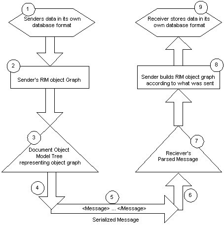
The steps for using the ITS to send information objects from the sending systems database to the receiving system's database ITS is represented in the diagram below and described as follows.
- The sending application ("sender") stores its information in its own database format
- The sender logically represents this information as a graph of RIM objects
- Using the form of the messages defined in the HMD and the algorithm defined by the ITS, the sender represents the RIM objects as an XML document, for example, by building a DOM tree
- The sender serializes the DOM tree, creating an XML Domain Content
- The sender transmits the Domain Content to the receiving application ("receiver") using TCP/IP, EMAIL, or some other message transport layer
- The receiver then unpacks the HL7 Domain Content from the transport layer
- The receiver removes the V3 message wrapper (s) and parses the encoded Domain Content using an off-the-shelf parser to create the DOM tree
- The receiver then interprets the DOM tree by "reversing" the ITS mapping, and perhaps building a RIM graph of received objects
- Finally, the receiver stores the data in its own database format
2.5
Data Types
Data types are the basic building blocks of attributes. They define the structural format of the data carried in the attribute and influence the set of allowable values an attribute may assume. Some data types have very little intrinsic semantic content and the semantic context for that data type is carried by its corresponding attribute. However HL7 also defines quite extensive data types such as PNMP, person Name Part, which provides all the structure and semantics to support a person name. Every attribute in the RIM is associated with one and only one data type, and each data type is associated with zero or many attributes.
Data types are discussed in two of the suite of documents that comprise the Version 3 Standard. The Data Types, Unabridged document provides a formal, rigorous definition of Version 3 data types and is intended for individuals who wish to explore data types in great detail. A less formal discussion of data types is included in the Implementation Technology Specification (ITS) for XML. It is envisaged that any particular ITS may not implement everything that is defined in the Data Types specification. The XML ITS is not an exception to this rule but nevertheless it is recommended as the best place for most HL7 readers to review the Data Types supported and how they are implemented. The table below groups Data Types.
| Data Type Category | Explanation | Example Data Types |
| Basic Data Types | These describe 31 of the 42 data types that HL7 defines | Text,Codes,Identifiers,Names,Addresses,Quantities |
| Generic Collections | Data Types where a number of values may be included. They are not complete data types as any collection will have an associated Data Type from one of the other Data Type groups listed here | Sequence, BAG and SET |
| Generic Type Extensions | Ability to extend existing Data Types through a formal extension language | Not supported in current XML ITS |
| Timing Specifications | All timing requirements | IVL, Time Interval |
A key capability with Data Types is the ability to refine a particular Data Type to a simpler one. For instance, the coded Data Type CV can be restricted down to CS, which supports only a Code and a Display Name. The XML ITS presents these refinements by always showing where a simpler Data Type is a restriction of a more complex Type. In the Visio tooling, the tool might first offer the more complex Data Type that has been defined for an Attribute, but then offers the ability to select any of the restriction options, making it easy to choose the simpler Data Type where this is appropriate.
A specific problem in interpreting the data types specification has been encountered with SET. The specification defines SET<1..1> as being a single instance of the attribute rather than a single SET, however this has often been misinterpreted.
2.6
Common Message Element Types
CMETs (Common Message Element Types) are a work product produced by a particular committee for expressing a common, useful and reusable concept. They are generally "consumed", or used by both the producing committee and other committees. Because they are intended for common use across messages produced by all committees, they are proposed to, reviewed by, and maintained by the CMET task force of the MnM committee. The CMET task force harmonizes and becomes steward for all CMETs.
A CMET can be envisioned as a message type fragment that is reusable by other message types. Any message type, including other CMETs, can reference a CMET. As an example, several committees may require the use of a common concept, that of a person in the role of a patient. A CMET can be defined to express this concept as a message type that clones a role played by a person, with all appropriate attributes. The CMET is then used to uniformly represent the concept for all interested committees.
A CMET is derived from a single D-MIM, defined by the producing committee. Its content is a direct subset of the class clones and attributes defined in that D-MIM, and does not include content from other D-MIMs (It does not “span” D-MIMs).
2.6.1
Semantic Categorization
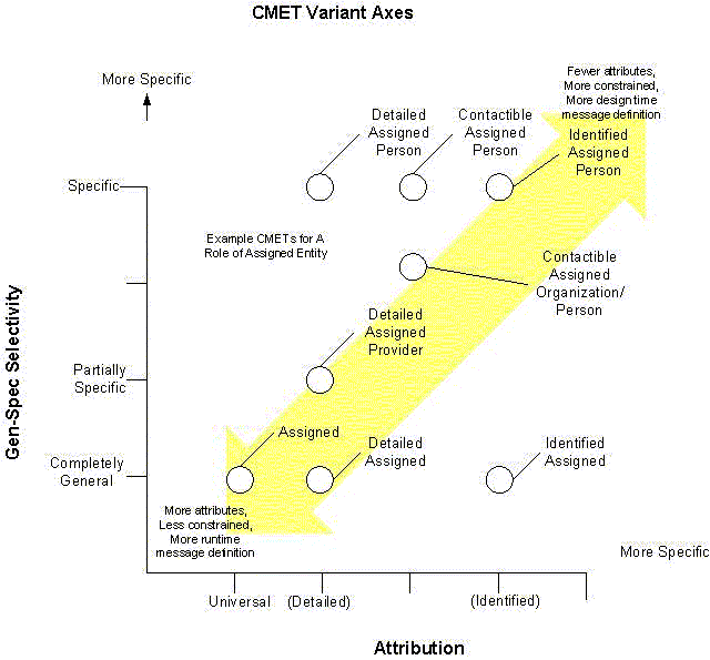
All CMETs can be categorized along two axes: Attribution and Gen-Spec Selectivity. The semantic intent of a CMET can be captured by viewing the CMET as a point in this space. Selectivity generally corresponds to an HMD level of specification, and the Attribution corresponds to the message type specification within the HMD.
The attribution axis corresponds to the CMET’s message type, and always contains at least three variants:
Axis 1: Attribution
- universal – this variant includes all attributes and associations present in the R-MIM. Any of non-mandatory and non-required attributes and/or associations may be present or absent, as permitted in the cardinality constraints.
- detailed – this variant is a proper subset of the universal variant, and provides a named variant that may restrict the universal variant. Any of non-mandatory and non-required attributes and/or associations may be present or absent, as permitted in the cardinality constraints.
- identified – this variant is a proper subset of universal and detailed. Only the mandatory and required attributes and associations may appear. Other variants may not be substituted at runtime.
Other variants that are proper subsets of universal may be defined and identified along this axis. These variants tighten constraints on one or more attributes/associations of the universal variant, falling somewhere between detailed and identified.
The Gen-Spec axis specifies the generalization-specialization hierarchies that are permissible in the message type. This corresponds to HMD level variants. There is always at least 1 variant, the fully general. Others may or may not be present
Axis 2: Gen-Spec selector
- general – this variant contains all permissible specializations of any gen-spec hierarchies represented in the R-MIM. This variant is used when the R-MIM designer wishes any of the listed specializations to be specified at runtime.
- specific – these variants specifically limit the available specializations for a message type to the one(s) specified. This variant is to be used when the message designer wishes to limit the available runtime message type choices.
2.6.2
Definition and Use of CMETs
CMETs are intended to express a common, reusable pattern. They are not intended to be used as a mechanism to simplify a D-MIM or R-MIM diagram, however. This means that a CMET should be expressed diagrammatically as a fully expanded instance diagram, in the D-MIM, where it is defined. An entry point is attached to this diagram to indicate the root class in the CMET.
The implication is that a CMET conveys reference information only, and is not intended to be used to carry update information in a message. Simply put, a CMET should be used to help identify the focal class that is the target of an update operation. A CMET should itself not carry update values.
Entry Point
The entry point for a CMET identifies the single point from which that CMET is "attached" to the containing or referencing message. The entry point is identified visually in the same manner as other entry points in a D-MIM diagram. The entry point identifies the RIM class from which the HMD for the CMET is started, known as the root class. When a CMET is used, the entry point identifier is inserted into the message at that point.
Type
The type of a CMET is the class type of the root class, together with any externally relevant attributes, such as class_code. Currently, CMETs are of type Act, Role, and Entity. For each of these types, the CMET type is the type of the Act, Role, or Entity, respectively.
Role Types
If a CMET is of type Role, it may "Participate", "Play or Participate", or "Scope or Participate". This means that a CMET of class type Role may be utilized as the target of a Participation, the target of a playing entity or a Participation, or the target of a scoping entity or a Participation. Note that it still may only have a single entry point, it cannot be the target of both a Participation and a playing entity at the same time; it may be either.
Exit Point
A CMET does not contain any exit points. This means that CMETs must be the "terminal" structure in a message type, i.e. one cannot leave a CMET and continue walking other portions of the R-MIM to derive an HMD.
Gen-Spec Hierarchies (Choices)
A CMET provides the capability to choose between instantiations of several specializations of a “Generalization-Specialization” hierarchy. This is known as a choice structure. Choice structures fall into two categories:
- The choice between multiple class types in the final message type is deferred until message instance creation time. In this case, the message instance must constrain the choice to a single element. In this case, the message instance builder simply chooses the appropriate message content at runtime.
- The choice is constrained in the R-MIM or HMD down to a single class type. The choice has been eliminated from the final message type, and is not available to the message instance builder. This method of constraint occurs as a result of choosing derivative CMET message types at design time.
2.6.3
Implementation Technology Specification Artifacts
The HL7 methodology produces an HMD and message type definitions that are then implemented by an ITS. In general, a schema defining the CMET message type is produced. This schema is then included in the message type schema for any message that utilizes the CMET. In this manner, as the CMET defines a schema for a message type, it is used to produce a message fragment that is used in a larger construct.
2.6.4
Visual and Tabular CMET Representation
CMETs are usually described by a visual diagram, down to the HMD level, and then specified exactly by a derived tabular representation, as with other message types. The following sections are illustrative:
D-MIM Diagram
CMETs are derived by an iterative refinement of a domain model. The top level, the domain model, expressed visually in a D-MIM diagram, contains multiple entry points. Each entry point is identified by a name and artifact id. Each entry point thus identifies the common base, or root class for R-MIMs, and HMDs. The R-MIMs and HMDs may derive any message type, including CMETs. At this level, the artifacts are R-MIM instance diagrams, representing abstract families of message types derived from that D-MIM.
CMET entry points appear on the D-MIM diagram to illustrate their grounding in the domain model.
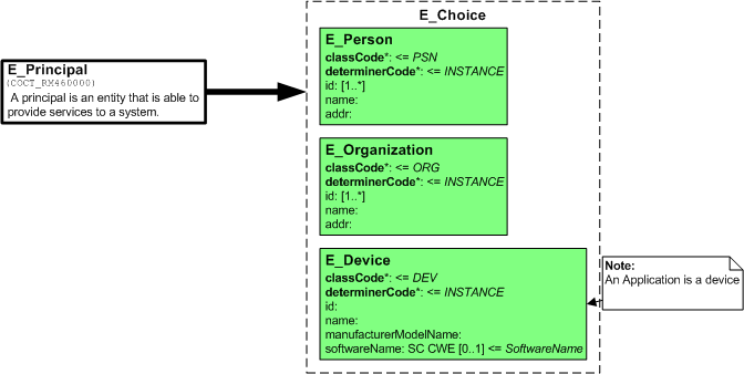
R-MIM Diagrams
A single Entry point on a DMIM can produce more than one R-MIM. Each R-MIM diagram represents the family of HMDs that describe the particular set of reusable concepts.
HMD Diagram
Each R-MIM diagram derives one or more HMD diagrams, each of which is an instance diagram of an HMD. HMD diagrams show entry point identifiers corresponding to the HMD that is derived, following the pattern "HDrrhh00".
Notice that the CMET R-MIM diagram shows the full set of constraints to be applied to the derived HMD and message type. In this respect, it is actually an object instance diagram of the HMD.
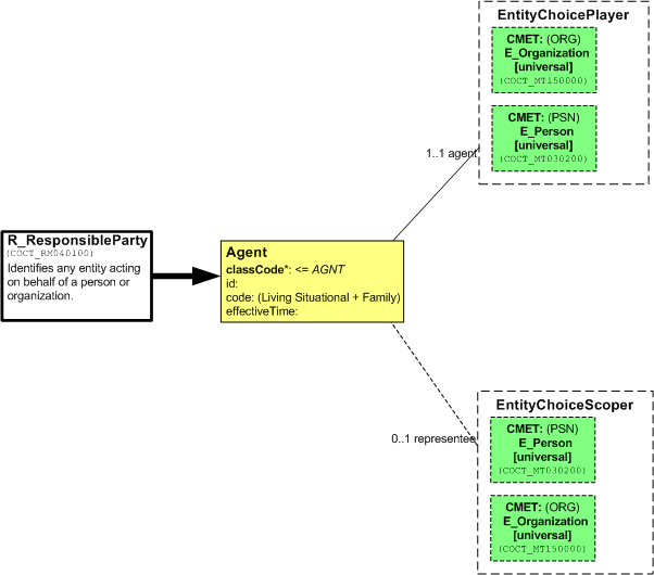
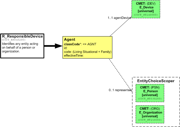
The following diagram shows two R-MIM or HMD diagrams derived from a common entry point. Each of the diagrams reduces the original diagram in order to specify a particular function. These reductions include omission of attributes (right) and the elimination of one of the pair of choices (both) in order to create a CMET for a corporate or personal account.
The first: R_Responsible Party is an agent role with a person or organization as playing and scoping entities.
In the second R-MIM, a device is the playing entity.
CMET Reference
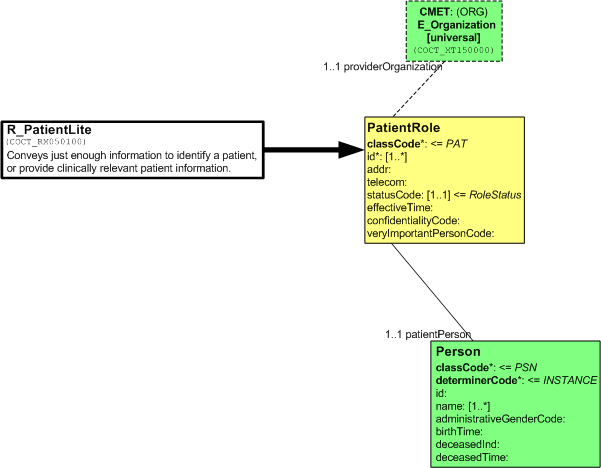
When a CMET is referenced, or used in another diagram, it is shown with a special notation, a box with dashed edges. It contains the name of the CMET, its artifact id, its class code and its level of attribution. Notice it is also color-coded in a manner consistent with its root class.
The following diagram shows one of the derived CMETs (HMD/MT) used in another R-MIM.
Tabular HMD Representation
The CMET described by the HMD level CMET diagram is alternatively represented fully by an HMD table. The following diagram illustrates a sample tabular representation for the above COCT_HD950100. Note that it is only a partial view of the HMD.
2.6.5
Examples
Refer to the Version 3 Guide Section 2.7 for examples of the XML Schema for the CMET R_Patient identified.
2.7
Refinement
Refinement is fundamental to many aspects of the HL7 V3 development approach. Key areas addressed elsewhere in the Guide are:-
- RIM refinement leading to D-MIMs and R-MIMs
- Refinement of R-MIMs to develop HMDs
Constraints are a third major aspect of refinement and are one of the main subjects of the Refinement, Constraint and Localization specification. Appearance constraints modify the status of a model or message element. Elements (defined as optional) may be made mandatory or they may be excluded. Cardinality constraints change the minimum or maximum number of times that a class attribute or an association may appear. Type constraints are about substituting a more restricted data type than the once specified for an attribute. Only specific substitutions may be made which are defined in the XML ITS, or more generally in the abstract Data Types specification. The Visio tools make this easy by showing what restrictions can be made for any particular attribute being constrained. A set of constraints on a message are called a constraint profile. In HL7 V3 constraint profiles must be derived from a balloted V3 message specification. Conformance is a process by which information system sponsors such as vendors communicate to a User organization how their products meet HL7 specifications. For future versions of V3, conformance claims will have to relate explicitly to the relevant V3 application roles for a particular message. This is called functional conformance. Additionally technical conformance must be shown in relation to defined V3 messages and one or more profiles of that message. Localization is a process that combines both constraints and extensions to existing V3 artifacts. Many organizations may carry out localization, but HL7 has explicitly defined when localizations are permitted and under what circumstances. Refer to the Localization part of the Refinement, Constraint, and Location Section.
2.8
Examples
This chapter contains an example of a V2.4 message, and an equivalent V3 representation of that message using the XML ITS with annotations. The chapter is based upon the revised XML ITS. However, the schema generator for this ITS is still somewhat unstable. Hence the example herein is subject to uncertainties caused by an interpretation of the ITS that may be flawed. The Publishing Committee will continue to refine this exemplary chapter and may re-issue it as a "patch" during the course of this ballot. The chapter will note those places where uncertain assumptions were made.
This chapter shows a V2.4 ORU^R01 for serum glucose and an equivalent V3 message instance. The various schema documents are not shown. Some of the significant mappings and content derivations are noted in comments in the V3 XML.
2.8.1
The V2.4 Message
        MSH|^~\&|GHH LAB|ELAB-3|GHH OE|BLDG4|200202150930||ORU^R01
             |CNTRL-3456|P|2.4<cr>
        PID|||555-44-4444||EVERYWOMAN^EVE^E^^^^L|JONES
             |196203520|F|||153 FERNWOOD DR.^^STATESVILLE^OH^35292||
             (206)3345232|(206)752-121||||
             AC555444444||67-A4335^OH^20030520<cr>
        OBR|1|845439^GHH OE|1045813^GHH LAB|1554-5^GLUCOSE|||200202150730|||||||||
             555-55-5555^PRIMARY^PATRICIA P^^^^MD^^LEVEL SEVEN HEALTHCARE, INC.
             |||||||||F||||||444-44-4444^HIPPOCRATES^HOWARD H^^^^MD<cr>
        OBX|1|SN|1554-5^GLUCOSE^POST 12H CFST:MCNC:PT:SER/PLAS:QN||^182|mg/dl|
             70_105|H|||F<cr>
2.8.2
The Root Element
The root element of the XML instance contains information necessary for its proper validation. The root element is Message, which is defined in the schema MCCI_MT000101.xsd. This release of the ITS (Ballot #3) uses a single Version 3 namespace for all instances.
        <?xml version="1.0" encoding="utf-8" standalone="no"?>
        <!--Example copyright 2002 by Health Level Seven, Inc. -->
        <Message xmlns="urn:hl7-org:v3"
           xmlns:xsi="http://www.w3.org/2002/XMLSchema-instance"
           xsi:schemaLocation="urn:hl7-org:v3/MCCI_MT000101
              MCCI_MT000101.xsd">
The element content of the root defines the sender and receiver in terms of applications, and also in terms of the organizations that are exchanging data. All IDs use OIDs as the method of ensuring global uniqueness. For the purposes of this example, all OIDs are identical – in a real message they would be unique.
Note that the root element uniquely identifies the message’s interaction identifier, in this case, POLB_IN004410, which identifies the message type, the trigger event, and the application roles.
The receiving application and organization are described in the executedByRcvApp element, the executedByRespondToOrg element and executedBySendApp identify the sending person, application, and organization. The receiver is the GHH_OE system in Bldg4. The sender is GHH_LAB at location E-LAB3.
The root element wraps the payload, which is the message control event for this message. It is contained in the has_payload_ControlActEvent.
           ...
           <id root="2.16.840.1.113883.1122" extension="CNTRL-3456"/>
           <!-- message ID, [msh.10]  -->
           <creation_time value="2002-08-16T14:30:35.16-06:00"/>
           <!-- [msh.7]  -->
           <version_id>3.0</version_id>
           <interaction_id root="2.16.840.1.113883"
              extension="POLB_IN004410"/>
           <!-- interaction id= Observation Event Complete,
              Notification  (POLB_IN004410) source=ORU^R01-->
                    Notification  (POLB_IN004410) source=ORU^R01-->
   <!-- [msh.9]  -->
   <processingCode code="P"/>
   <!-- processing code, [msh.11] -->
   <processingModeCode code="I"/>
   <!-- processing ID, [msh.11] -->
   <acceptAckCode code="ER"/>
   <!-- [msh.15]  -->
   <!-- errors only -->
   <applicationAckCode code="ER"/>
   <!-- [msh.16]  -->
            <communicationFunctionRsp>
              <!-- presume "respond_to" is a sending contact -->
              <type_cd code="RSP"/>
              <telecom use="WP" url="555-555-5555"/>
              <servedBy>
                 <nm xsi:type="dt:PN">
                    <dt:family>Hippocrates</dt:family>
                    <dt:given>Harold</dt:given>
                    <dt:given>H</dt:given>
                    <dt:suffix qualifier="AC">MD</dt:suffix>
                 </nm>
                 <telecom use="WP" url="555-555-5555"/>
              </servedBy>
           </executedByRespondToOrg>
           <executedBySendApp>
              <type_cd code="SND"/>
              <telecom value="127.127.127.255"/>
              <servedBy>
                 <!-- sending application, [msh.3] -->
                 <id extension="GHH LAB" root="2.16.840.1.113883.1122"/>
                 <nm use="L">
                    <given>An Entity Name</given>
                 </nm>
                 <telecom value="555-555-2005" use="H"/>
                 <agencyFor>
                    <!-- sending facility [msh.4]  -->
                    <representedOrganization>
                       <id nullFlavor="OTH"/>
                    </representedOrganization>
                 </agencyFor>
                 <presence>
                    <location>
                       <id root="2.16.840.1.113883.1122"
                          extension="ELAB-3"/>
                       <nm xsi:type="dt:TN">GHH Lab</nm>
                    </location>
                 </presence>
              </servedBy>
           </executedBySendApp>
           <executedByRcvApp>
              <type_cd code="RCV"/>
              <telecom value="127.127.127.0"/>
              <servedBy>
                 <!-- Receiving application, [msh.5] -->
                 <id root="2.16.840.1.113883.1122"
                    extension="GHH OE"/>
                 <nm use="L">
                    <given>An Entity Name</given>
                 </nm>
                 <telecom value="555-555-2005" use="H"/>
                 <agencyFor>
                    <representedOrganization>
                       <id root="2.16.840.1.113883.19.3.1001"/>
                       <nm xsi:type="TN">GHH Outpatient Clinic</nm>
                    </representedOrganization>
                 </agencyFor>
                 <presence>
                    <location>
                       <id root="2.16.840.1.113883.1122"
                          extension="BLDG4"/>
                       <nm xsi:type="TN">GHH Outpatient Clinic</nm>
                    </location>
                 </presence>
              </servedBy>
           </executedByRcvApp>
           <has_payload_ControlActEvent xsi:type="MCAI_HD700200">
              ...
           </has_payload_ControlActEvent>
        </Message>
2.8.3
The Control Act
The message control act is yet another wrapper around the actual message. This has a class_cd of CEVN, and indicates no response to the message is expected. The element tags verifier denote the supervisor or responsible person for this lab result, and the interactionTarget act relationship ties the control event wrapper to the target message, of type POLB_MT004401.
           <has_payload_ControlActEvent xsi:type="MCAI_HD700200">
              <!--  Message interaction control event wrapper,
                 substituted by the sender -->
              <!-- act control event  -->
              <response_cd code="N"/>
              <verifier>
                 <participant_COCT_MT090100>
                    <id root="2.16.840.1.113883.1122"
                       extension="444-444-4444"/>
                 </participant_COCT_MT090100>
              </verifier>
              <interactionTarget xsi:type="POLB_MT004101">
                 ...
              </interactionTarget>
           </has_payload_ControlActEvent>
2.8.4
The Message Body
The "Domain Content" starts with its own root element – interactionTarget. The elements within specify the type of observation, the ID, the time of the observation, status_cd, and the results. The value for the actual result is shown in the value element. The interpretation_cd element shows that the value has been interpreted as high (H), while referenceRange provides the normal values for this particular observation.
The patient and the responsible provider parts are discussed further in their own sections, while the rest of the information is shown here:
        <interactionTarget xsi:type="POLB_MT004101">
           <ObservationEvent>
              <!--- ID is the filler order number ... -->
              <id root="2.16.840.1.113883.1122"
                 extension="1045813"
                 assigningAuthorityName="GHH LAB"/>
              <cd code="1554-5" codeSystemName="LN"
                 displayName="GLUCOSE^POST 12H
                    CFST:MCNC:PT:SER/PLAS:QN"/>
              <status_cd code="completed"/>
              <!-- time the sample was taken -->
              <effective_time>
                 <dt:center value="2002-02-15T07:30:00"/>
              </effective_time>
              <!-- time of the actual lab test -->
              <activity_time>
                 <dt:center value="2002-02-15T08:30:00"/>
              </activity_time>
              <priority_cd code="R"/>
              <value xsi:type="dt:PQ" value="182" unit="mg/dL"/>
              <interpretation_cd code="H"/>
              <participant>
                 ...
              </participant>
              <patient>
                 <!-- PID -->
                 <patient>
                    ...
                 </patient>
              </patient>
              <inFulfillmentOf>
                 <!-- placer order -->
                 <priorObservationOrder>
                    ...
                 </priorObservationOrder>
              </inFulfillmentOf>
              <referenceRange>
                 <referenceObservationEventCriterion>
                    <value xsi:type="dt:IVL_PQ">
                       <dt:low value="70" unit="mg/dL"/>
                       <dt:high value="105" unit="mg/dL"/>
                    </value>
                 </referenceObservationEventCriterion>
              </referenceRange>
           </ObservationEvent>
        </interactionTarget
2.8.5
The Original Order
The original order for the laboratory observation is referenced by the FLFS act relationship named priorObservationOrder, which identifies the order by placer numbe. This number should be used by the receiver to match the results to the order. The ordering provider, Dr. Patricia Provider, is included with her ID and name. Note that there are two levels of information present, the practitioner level and the person level. The ID is on the practitioner level, while the name is on the person level.
        <inFulfillmentOf>
           <!-- placer order -->
           <priorObservationOrder>
              <id root="2.16.840.1.113883.1122"
                 extension="845439"
                 assigningAuthorityName="GHH OE"/>
              <cd code="1554-5" codeSystemName="LN"
                 displayName="Serum Glucose"/>
              <participant>
                 <type_cd code="RESP"/>
                 <assignedEntity>
                    <id root="2.16.840.1.113883.1122"
                       extension="555-555-5555"/>
                    <assignee_Person>
                       <nm use="L" xsi:type="dt:PN">
                          <dt:family>Primary</dt:family>
                          <dt:given>Patricia</dt:given>
                          <dt:given>P</dt:given>
                          <dt:suffix qualifier="AC">
                             MD</dt:suffix>
                       </nm>
                    </assignee_Person>
                 </assignedEntity>
              </participant>
           </priorObservationOrder>
        </inFulfillmentOf>
2.8.6
The Performing Provider
The performing provider, Mr. Harold H Hippocrates, is included with his ID and name. In a similar fashion to that of the ordering provider, there are two levels of information present, the practitioner level and the person level. The ID is on the practitioner level, while the name is on the person level.
        <participant>
           <!-- this is the signatory -->
           <type_cd code="AUT"/>
           <!-- time of signature -->
           <time value="2002-08-16T09:30:00"/>
           <mode_cd code="WRITTEN"/>
           <!-- signature is on file -->
           <signature_cd code="S"/>
           <assignedEntity>
              <id root="2.16.840.1.113883.1122"
                 extension="444-444-4444"/>
              <assignee_Person>
                 <nm use="L" xsi:type="dt:PN">
                    <dt:family>Hippocrates</dt:family>
                    <dt:given>Harold</dt:given>
                    <dt:given>H</dt:given>
                    <dt:suffix qualifier="AC">MD</dt:suffix>
                 </nm>
              </assignee_Person>
           </assignedEntity>
        </participant>
2.8.7
The Patient
The patient, Eve E. Everywoman, is also represented with two levels - the patient and the person. The available elements within the patient element are few since this is part of a closely-coupled message (e.g. there is no space for an address). On the other hand, the id is required with the name, thus providing for at least some form of error checking. Again, there are IDs on each level - the pre-assigned patient ID is on the patient level, while a driver’s license number is present on the person level as a person ID.
        <patient>
           <patient>
              <id root="2.16.840.1.113883.1122"
                 extension="375913"/>
              <patient_Person>
                 <!-- Ohio DL -->
                 <pat:id root="2.16.840.1.113883.1122"
                    extension="444-22-2222"
                    validTime="-2003-05-20"
                    assigningAuthorityName="OH"/>
                 <pat:nm use="L" xsi:type="PN">
                    <dt:family>Everywoman</dt:family>
                    <dt:given>Eve</dt:given>
                    <dt:given>E</dt:given>
                 </pat:nm>
              </patient_Person>
           </patient>
        </patient>
2.8.8
The Complete observation.xml Example
        <?xml version="1.0" encoding="utf-8" standalone="no"?>
        <!--Example copyright 2002 by Health Level Seven, Inc. -->
        <Message xmlns="urn:hl7-org:v3"
           xmlns:xsi="http://www.w3.org/2002/XMLSchema-instance"
           xsi:schemaLocation="urn:hl7-org:v3/MCCI_MT000101
              MCCI_MT000101.xsd">
           <id root="2.16.840.1.113883.1122" extension="CNTRL-3456"/>
           <!-- message ID, [msh.10]  -->
           <creation_time value="2002-08-16T14:30:35.16-06:00"/>
           <!-- [msh.7]  -->
           <version_id>3.0</version_id>
           <interaction_id root="2.16.840.1.113883"
              extension="POLB_IN004410"/>
           <!-- interaction id= Observation Event Complete,
              Notification  (POLB_IN004410) source=ORU^R01-->
           <processing_cd code="P"/>
           <!-- processing code, [msh.11] -->
           <accept_ack_cd code="ER"/>
           <!-- errors only -->
           <application_ack_cd code="ER"/>
           <executedByRespondToOrg>
              <!-- presume "respond_to" is a sending contact -->
              <type_cd code="RSP"/>
              <telecom use="WP" url="555-555-5555"/>
              <servedBy>
                 <nm xsi:type="dt:PN">
                    <dt:family>Hippocrates</dt:family>
                    <dt:given>Harold</dt:given>
                    <dt:given>H</dt:given>
                    <dt:suffix qualifier="AC">MD</dt:suffix>
                 </nm>
                 <telecom use="WP" url="555-555-5555"/>
              </servedBy>
           </executedByRespondToOrg>
           <executedBySendApp>
              <type_cd code="SND"/>
              <telecom value="127.127.127.255"/>
              <servedBy>
                 <!-- sending application, [msh.3] -->
                 <id extension="GHH LAB" root="2.16.840.1.113883.1122"/>
                 <nm use="L">
                    <given>An Entity Name</given>
                 </nm>
                 <telecom value="555-555-2005" use="H"/>
                 <agencyFor>
                    <!-- sending facility [msh.4]  -->
                    <representedOrganization>
                       <id nullFlavor="OTH"/>
                    </representedOrganization>
                 </agencyFor>
                 <presence>
                    <location>
                       <id root="2.16.840.1.113883.1122"
                          extension="ELAB-3"/>
                       <nm xsi:type="dt:TN">GHH Lab</nm>
                    </location>
                 </presence>
              </servedBy>
           </executedBySendApp>
           <executedByRcvApp>
              <type_cd code="RCV"/>
              <telecom value="127.127.127.0"/>
              <servedBy>
                 <!-- Receiving application, [msh.5] -->
                 <id root="2.16.840.1.113883.1122"
                    extension="GHH OE"/>
                 <nm use="L">
                    <given>An Entity Name</given>
                 </nm>
                 <telecom value="555-555-2005" use="H"/>
                 <agencyFor>
                    <representedOrganization>
                       <id root="2.16.840.1.113883.19.3.1001"/>
                       <nm xsi:type="TN">GHH Outpatient Clinic</nm>
                    </representedOrganization>
                 </agencyFor>
                 <presence>
                    <location>
                       <id root="2.16.840.1.113883.1122"
                          extension="BLDG4"/>
                       <nm xsi:type="TN">GHH Outpatient Clinic</nm>
                    </location>
                 </presence>
              </servedBy>
           </executedByRcvApp>
           <has_payload_ControlActEvent xsi:type="MCAI_HD700200">
              <!--  Message interaction control event wrapper,
                 substituted by the sender -->
              <!-- act control event  -->
              <response_cd code="N"/>
              <verifier>
                 <participant_COCT_MT090100>
                    <id root="2.16.840.1.113883.1122"
                       extension="444-444-4444"/>
                 </participant_COCT_MT090100>
              </verifier>
              <interactionTarget xsi:type="POLB_MT004101">
                 <ObservationEvent>
                    <!--- ID is the filler order number ... -->
                    <id root="2.16.840.1.113883.1122"
                       extension="1045813"
                       assigningAuthorityName="GHH LAB"/>
                    <cd code="1554-5" codeSystemName="LN"
                       displayName="GLUCOSE^POST 12H
                          CFST:MCNC:PT:SER/PLAS:QN"/>
                    <status_cd code="completed"/>
                    <!-- time the sample was taken -->
                    <effective_time>
                       <dt:center value="2002-02-15T07:30:00"/>
                    </effective_time>
                    <!-- time of the actual lab test -->
                    <activity_time>
                       <dt:center value="2002-02-15T08:30:00"/>
                    </activity_time>
                    <priority_cd code="R"/>
                    <value xsi:type="dt:PQ" value="182" unit="mg/dL"/>
                    <interpretation_cd code="H"/>
                    <participant>
                       <!-- this is the signatory -->
                       <type_cd code="AUT"/>
                       <!-- time of signature -->
                       <time value="2002-08-16T09:30:00"/>
                       <mode_cd code="WRITTEN"/>
                       <!-- signature is on file -->
                       <signature_cd code="S"/>
                       <assignedEntity>
                          <id root="2.16.840.1.113883.1122"
                             extension="444-444-4444"/>
                          <assignee_Person>
                             <nm use="L" xsi:type="dt:PN">
                                <dt:family>Hippocrates</dt:family>
                                <dt:given>Harold</dt:given>
                                <dt:given>H</dt:given>
                                <dt:suffix qualifier="AC">MD</dt:suffix>
                             </nm>
                          </assignee_Person>
                       </assignedEntity>
                    </participant>
                    <patient>
                       <!-- PID -->
                       <patient>
                          <id root="2.16.840.1.113883.1122"
                             extension="375913"/>
                          <patient_Person>
                             <!-- Ohio DL -->
                             <pat:id root="2.16.840.1.113883.1122"
                                extension="444-22-2222"
                                validTime="-2003-05-20"
                                assigningAuthorityName="OH"/>
                             <pat:nm use="L" xsi:type="PN">
                                <dt:family>Everywoman</dt:family>
                                <dt:given>Eve</dt:given>
                                <dt:given>E</dt:given>
                             </pat:nm>
                          </patient_Person>
                       </patient>
                    </patient>
                    <inFulfillmentOf>
                       <!-- placer order -->
                       <priorObservationOrder>
                          <id root="2.16.840.1.113883.1122"
                             extension="845439"
                             assigningAuthorityName="GHH OE"/>
                          <cd code="1554-5" codeSystemName="LN"
                             displayName="Serum Glucose"/>
                          <participant>
                             <type_cd code="RESP"/>
                             <assignedEntity>
                                <id root="2.16.840.1.113883.1122"
                                   extension="555-555-5555"/>
                                <assignee_Person>
                                   <nm use="L" xsi:type="dt:PN">
                                      <dt:family>Primary</dt:family>
                                      <dt:given>Patricia</dt:given>
                                      <dt:given>P</dt:given>
                                      <dt:suffix qualifier="AC">
                                         MD</dt:suffix>
                                   </nm>
                                </assignee_Person>
                             </assignedEntity>
                          </participant>
                       </priorObservationOrder>
                    </inFulfillmentOf>
                    <referenceRange>
                       <referenceObservationEventCriterion>
                          <value xsi:type="dt:IVL_PQ">
                             <dt:low value="70" unit="mg/dL"/>
                             <dt:high value="105" unit="mg/dL"/>
                          </value>
                       </referenceObservationEventCriterion>
                    </referenceRange>
                 </ObservationEvent>
              </interactionTarget>
           </has_payload_ControlActEvent>
        </Message>
3
HL7 Messaging Components
3.1
Navigating around a message specification
The HL7 Messaging Components section of the V3 Guide is provided to help readers of the V3 standards understand the messages and supporting content submitted by the technical committees. This information is contained in each of the domain chapters.
V3 introduces a new approach to HL7 message development. To assist with the comprehension of this new approach, the domain chapters begin with a high-level overview and progressively drill down to lower levels of messaging detail (including storyboards, applications roles, trigger events, D-MIMs, R-MIMs, HMDs, message types, and interactions). The following is the structure of the table of contents for each of the domains.
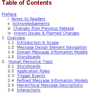
Each chapter begins with an overview of the domain and the scope of the messages defined there. Since a "big picture" understanding of the particular domain is crucial to understanding the messages defined within it, each domain chapter provides a Storyboard section. This section contains both a narrative and a diagrammatic representation of the messages that will be exchanged and the types of healthcare applications that will exchange the messages defined in the chapter, and illustrates the overall flow of the messages between these applications, including the order of such information flows.
The Message Design Element Navigation (below) provides a quick overview of the Message Types, HMDs and R-MIMs relationship to each other with hyperlinks to the actual artifact definitions within the chapter. The navigation display uses a "tree-view" control that allows the user to expand or collapse a hierarchy of elements. If the symbol to the left of a row includes the plus sign ("+"), clicking on the row will expand the row to show its children. Conversely, if the symbol at left is the minus sign ("-"), clicking on the row will hide the dependent, child rows below that row. If the symbol at the left of a row is a dot, then the row has no children to be displayed.
Within each domain the content has been revised from January 2004 to provide the following structure. First information that applies to the whole domain. This is defined in the next two paragraphs. This is followed by message definitions grouped by "topic". Each topic is in fact covers all the definitions in a particular sub-domain. Topic names and the number of topics defined are left to each HL7 committee.
The Domain Information Model (D-MIM) is presented first in each domain, providing a graphical and narrative detail of the scope of the domain. The D-MIM is the first in the series of information models presented in each domain chapter. The D-MIM provides a diagrammatic representation of only those classes, attributes and associations that are required for the messages defined by the domain. The D-MIM is a subset of the RIM but uses specific conventions to represent artifacts such as CMETs and various types of associations. Once the classes, attributes and associations for a particular domain have been isolated via the D-MIM, the next logical step is to extract, from the D-MIM, the set of classes, attributes and associations required for an HMD or set of HMDs that originate from the same root class. These extractions are referred to as R-MIMs (Refined Message Information Models), which are a subset of and use the same conventions as the domain D-MIM.
The second element in the domain is one or more domain-level storyboards. Each storyboard includes a diagrammatic representation, called an Interaction Diagram. This diagram depicts healthcare applications by the generic roles they play, such as Clinical Document Repository or Order Placer. These generic roles are known as application roles and are depicted in the diagram as vertical lines. Each information flow between two application roles is an interaction and identified on the Storyboard diagram as a horizontal, arrowed line. Interactions describe the purpose of information flow. Create Patient Billing Account and Delete Patient Billing Account are examples of interactions found in the HL7 V3 messaging standard. Once the overall picture of data exchange is presented, the Storyboard section continues with a narrative describing how the interactions might unfold in real life. Following the narrative is a description of each application role. Storyboards may be represented for the entire domain, or may be specific to a topic within the domain.
All remaining material is grouped under a topic name. Some committees will define a large number of topic names. Other committees may have very few. It is completely up to a committee to decide. Within each topic, message specification is grouped under six headings. Each heading is decribed in the following paragraphs
Storyboard: For each topic, one or more storyboards scope the specifications that follow
Application Roles: The application roles applicable to this topic are defined.From the Application Role definitions, the reader can identify the purpose for information flow between two healthcare applications and the roles that those healthcare applications play in that exchange
Trigger events: . The question of what prompts information exchange between two applications is answered by the trigger event. This part of the topic specification is a list/description of the trigger events defined by the domain.
The final products, the message types, are derived by the intersection of specific interactions, application roles, and trigger events. The remaining portions of the domain chapters show, through a series of information models, how the resulting message types are derived.
The data represented in the R-MIM are ordered in a tabular format known as a Hierarchical Message Description (HMD). Each HMD produces a single base message template from which the specific message types are drawn. A message type represents a unique set of constraints applied against a particular HMD. Message types are presented in both grid and table view as well as an Excel spreadsheet. In addition, a link to the XML schema used to validate any message conforming to the message type is provided along with an XML example. The domain chapters close with a section that groups message data by interaction, giving the sending and receiving applications roles, trigger event and message type for each.
In the final part of the domain specifications, the Common Message Elements Indexes list the CMETs derived from the domain's D-MIM and the CMETs referenced in each HMD defined within the D-MIM. The index links to the Common Message Element Type Domain content.
The Interaction Index is designed to provide useful cross-references between the documents. The Interaction Indexes list the Interactions used against each Application Role, Trigger Event and Message Type.
The Domain Glossary contains terms that are defined in this domain, as well as terms that are common to all domains.
3.1.1
Artifact Identification System
Within the HL7 V3 standards the components that make up the documentation are each referred to as ‘artifacts’. This includes, storyboards, application roles, trigger events, D-MIMs, R-MIMs, HMDs, message types and interactions are artifacts. Each artifact is submitted by a Technical Committee and given a unique identifier that is assigned by concatenating the Sub-Section, Domain and Artifact code with a 6-digit, non-meaningful number.
The Sub-Section and Domain Codes assigned include:
| Health & Clinical Management Domains |
| Subsection: Operations (PO) Domain: Laboratory (POLB) Domain: Pharmacy (PORX) |
| Subsection: Records (RC) Domain: Medical Records (RCMR) |
| Administrative Management Domains |
| Subsection: Practice (PR) Domain: Patient Administration (PRPA) Domain: Scheduling (PRSC) Domain: Personnel Management (PRPM) |
| Subsection: Financial (FI) Domain: Claims & Reimbursement (FICR) Domain: Accounting & Billing (FIAB) |
| Specification Infrastructure |
| Subsection: Message Control (MC) Domain: Message Control Infrastructure (MCCI) Domain: Message Act Infrastructure (MCAI) |
| Subsection: Master File (MF) Domain: Master File Management Infrastructure (MFMI) |
| Subsection: Query (QU) Domain: Query Infrastructure (QUQI) |
| Subsection: Common Content (CO) Domain: Common Message Elements (COCT) Domain: Common Message Content (COMT) |
Each Health & Clinical and Administrative Management domain may contain domain specified content for Query and Master File Subsections as well as general domain information.
The following Artifact Codes have been assigned:
| Artifact | Code |
|---|---|
| Application Role | AR |
| D-MIM (Domain Information Model) | DM |
| HMD (Hierarchical Message Descriptor) | HD |
| Interaction | IN |
| Message Type | MT |
| R-MIM (Refined Message Information Model) | RM |
| Storyboard | ST |
| Storyboard Narrative | SN |
| Trigger Event | TE |
The current version of HL7 3.x supports only one Realm identified as the “Universal Realm” with the code “UV”.
The Version Number is assigned once an artifact successfully passes membership ballot. Currently all artifacts are assigned the version 00 indicating that they are undergoing balloting.
An application role submitted by the Patient Administration domain will have the following unique artifact identifier:
PRPA_AR00001UV00
Where:
PR = Subsection: Practice
PA = Domain: Patient Administration
AR = Artifact: Application Role
00001 = 6 digit non-meaningful number assigned by the TC to ensure uniqueness
UV = Realm (the only current value is UV for universal)
00 = Current version number
As you browse through the ballot documents, you will notice that most artifact identifiers are hyperlinks that connect to the particular artifact in question.
The remaining chapters of this section of the V3 Guide explain each of these artifacts.
3.1.2
Describing V3 message artifacts
Unambiguous description of V3 artifacts is achieved by defining a “Structured Sort Name” for each artifact. This unique structured name is used to identify the relationship of the artifact to others so that it is sorted appropriately in the publications database. which acts both as a repository and the basis on which specifications and ballot material can be presented in a logical order.
Some types of artifacts also have a “Title Name” that is designed to be ‘human friendly’ and will appear in the table of contents and as the title for the artifact. The title name is not guaranteed to be unique, but may be a handy ‘human understandable’ tool for identifying the artifact. When a Title Name has also been defined for an artifact the Structured Sort Name is shown underneath the Title name for reference. Artifacts that do not have separate title names will have the Structured Sort Name appear in the table of contents and in the title bar.
Note that the Artifact Code, rather than the Structured Sort Name or Title Name, is always the best key to use when referencing an artifact as this will not change over time and is guaranteed to be unique.
The following table provides the algorithm for defining the Structured Sort Name for each type of artifact:
| Artifact | Structured Sort Name Algorithm |
|---|---|
| Storyboard | [Base Class] [Free-Text] |
| Storyboard Narrative | [Base Class] [Free-Text] |
| Application Role - Unhidden | [Base Class] [Free-Text] |
| Application Role - Hidden | [Base Class] [Mood][Capability][Stereotype][Environment] |
| Application Role - Query | [Base Class] [Mood] [Qualifier] Query Placer or[Base Class] [Mood] [Qualifier] Query Fulfiller |
| Trigger Event | [Base Class] [Mood] [State Transition][Qualifier][Action] |
| Trigger Event - Query | [Base Class] [Mood] [Qualifier] Query or[Base Class] [Mood] [Qualifier] Query Response |
| D-MIM | [Domain name] Domain Model |
| R-MIM | [Base Class] [Mood] |
| HMD | [Base Class] [Mood] [State Transition] |
| Message Type | [Base Class] [Mood] [State Transition] [Environment] |
| Interaction | [Base Class] [Mood] [State Transition] [Action][Environment] |
| Interaction - Query | [Base Class] [Mood] [Qualifiers] Query or[Base Class] [Mood] [Qualifiers] Query Response |
The following table provides an explanation and the valid values and their sort order for each component of the Structured Sort Name:
Base Class
Definition: Specified by the technical committee as a primary sort key to categorize the content of the domain.
Sort Order: Defined by technical committees as appropriate for the domain.
Free Text
Definition: The Structured Sort Name for some artifacts is only mandated for state transition-related names such as trigger events, allowing any technical committee to define a free text name for the artifact. The Structured Sort Name must still be unique. Some technical committees are not following these rules for trigger events at present (which requires all but one name component to be present). As a result trigger event structured names are not as easily readable as they should be.
Sort Order: Sorted alphabetically.
Qualifiers
Definition: Uniquely identifies the query and will be based on the parameters and response payload within the query.
Sort Order: Sorted alphabetically.
Environment
Definition: The technical committee may define the environment to be any value appropriate to the domain.
Sort Order: Sorted alphabetically.
Mood
Definition: This element is a further qualification of the base class, when the base class is an Act. It refers to the value of the mood code (see RIM definition) for the base class. The principal values are Event, Order, Intent and Proposal.
| Sort Order and Valid Values |
|---|
|
Action
Definition: The Action is a qualifier of interactions. It reflects the specific type of communication involved in a particular Interaction.
| Sort Order and Valid Values |
|---|
|
Application Role Stereotypes
Definition: The term stereotype, which is extensively used in UML applications, is only currently used in HL7 V3 for application role stereotypes. The term is generally used to refer to a closely related group of items within a particular categorisation. In application roles, there are currently six stereotypes defined based upon the capability of one application to interact with another. At the base level, applications simply send or receive notifications of events (Informer and Tracker). At the next level applications expect an action and response from the application that receives the notification (Placer and Fulfiller). At the final level, applications are capable of handling confirmations of requests (Confirmer and Confirmation Receiver). Use of these standardised stereotype names is intended to assist in the definition and use of application roles generally. The stereotypes do not form an exclusive set of names for application roles.
| Sort Order and Valid Values |
|---|
|
State Transition
Definition: The values allowed in this component are derived from the RIM State Transition Models as defined by the HL7 harmonization process and documented in the RIM part of the standard.
| Sort Order and Valid Values |
|---|
|
Capability Related to Acts in Mood "Event"
Definition: Describes the functions that the application is capable of performing in terms of state transition if the artifact contains a mood code of Event as defined in the [Mood] component of the Structured Sort Name.
| Sort Order and Valid Values |
|---|
|
Capability Related to Acts in Moods Other Than "Event"
Definition: Describes the functions that the application is capable of performing in terms of state transition if the artifact contains a mood code other than Event as defined in the [Mood] component of the Structured Sort Name.
| Sort Order and Valid Values |
|---|
|
Any Structured Sort Name components that do not follow the above guidelines or include invalid components will be sorted alphabetically.
3.2
Storyboard and Storyboard Narrative
The storyboard concept is borrowed from the movie and animation industry, and is useful to the development of HL7 messages for the same reasons proven in that industry:
A storyboard depicts a story using a series of "snapshots" or events in chronological sequence;
Each snapshot represents a recognizable, meaningful moment in the sequence of events that the reader must know about to understand the overall sequence and result;
Each snapshot illustrates the key participants in the storyboard and their interaction with other players;
The whole series of snapshots provides a coherent description of a complete process or activity.
A storyboard consists of a short description of its purpose and an interaction diagram that shows the progression of interactions between the application roles. A storyboard narrative is a description of a real-life event that provides the necessary context for the development of a specific interaction described in the storyboard. The process of storyboarding lays the foundation for describing HL7 messages and their content.
3.2.1
Storyboard Format
The V3 Storyboards are comprised of the following sections:
Name - The name is simply a short, descriptive phrase.
Artifact ID - The ID is a 16-character code with ST as the Artifact code.
Purpose - The purpose is a short narrative that describes the generic set of actions that the storyboard represents.
A sample showing the storyboard elements described above is provided in the figure below:
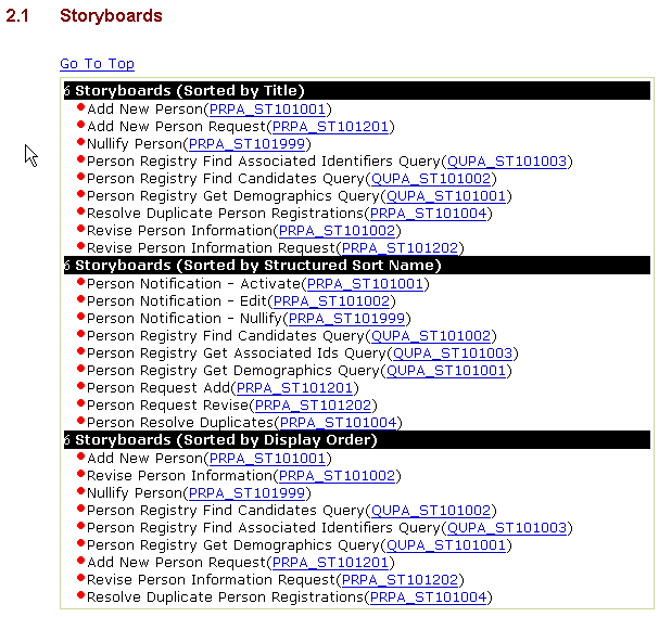
Interaction Diagram - The Interaction Diagram shows the interactions between the application roles. These interactions are typically depicted using a sequence diagram. A sample interaction diagram is provided below. Note that the boxes at the top of the diagram and the vertical lines associated with them represent application roles (the types of systems that send and receive the messages). Starting from the upper left corner and moving down to the lower right corner, the arrows show the interactions between the various application roles. The names and associated artifact codes of those interactions are noted within the arrowed lines.
List of interactions - Immediately following the Interaction Diagram is a list of the Interactions

One or more Interaction Narratives - Following the list of interactions is a narrative description of each interaction contained in the interaction list. Note that the Narrative has a name and an artifact number. The narrative is a prose example of how the interaction may unfold in the real word. A sample narrative is provided below:
3.3
Application Roles
Application roles represent a set of communication responsibilities that might be implemented by an application. Thus they describe system components or sub-components that send and/or receive interactions.
3.3.1
Normative status
Despite the fact that the application roles are documented in the normative domain specifications, the HL7 Technical Steering Committee has declared that applications roles shall be informative, not normative, in Release 1 of Version 3. The reason for this declaration is that HL7 wishes to see a number of Version 3 implementations before it specifies the content and granularity of application roles. The earliest that application roles could become normative is Release 2. Despite this restriction, the conformance specification describes the prospective use of application roles as the basis of conformance claims.
3.3.2
Responsibilities
As an HL7 interaction is defined, one application role is assigned responsibility for sending (initiating) that interaction, and one application role is assigned responsibility to receive that interaction and undertake the appropriate responses. The sending and receiving responsibilities for a particular interaction may both be assigned to a single application role.
3.3.3
Documentation
The application roles were apparent on the Interaction Diagram found in the Storyboard chapter. The boxes at the top of the diagram and the corresponding vertical lines represent application roles. Each of the application roles shown on the Interaction Diagram has an entry within the domain chapter. Note that like many of the other artifacts, the application role has a name, an artifact ID and a description. It also contains a Structured Name, which is used to sort the application roles within a particular domain into a logical sequence.
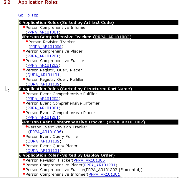
3.4
Trigger Events
A trigger event is an explicit set of conditions that initiate the transfer of information between system components (application roles). It is a real-world event such as the placing of a laboratory order or drug order. The trigger event must be systematically recognizable by an automated system.
Within the V3 standards, trigger events are defined by a name, an artifact ID, a description, and a Type. The Structured Name is used to sort the trigger events within a particular domain into a logical sequence and is assigned by the Technical Committee.The required Structured Name for a trigger event must comprise Mood,State -Transition and Type, however note that all committees are not yet following these recommendations in current ballots.
In the V3 standard, most trigger events will be a specifiedType, from the following list:
- Interaction Based: Trigger events can be based on another interaction. For example, the response to a query (which is an interaction) is an Interaction Based trigger event.
- State-Transition Based: Trigger events resulting from a state transition as depicted in the State Transition Model for a particular message interaction. The trigger for canceling a document, for example, may be considered a State Transition Based trigger event
- User Request Based: Trigger events may be based on a user request. For example, the trigger event that prompts a system to send all accumulated data to a tracking system every 12 hours is considered User Based.
Most trigger events are State-Transition based and will be encountered when reading the dynamic message model information defined to support a particular message interaction. Some trigger events may be based on more than one state transition, which are assumed to occur simultaneously. In some cases, trigger events may not fall into any of the three categories defined in the above list. In these cases, Unspecified will appear as the Type. The trigger event Type, when specified, affects the responsibilities of the interactions initiated by that trigger event.
The figure below illustrates how trigger events are documented and represented within the HL7 Version 3 Specifications:
When defining custom Trigger Event refinements, technical committees are encouraged to construct an "expository" R-MIMs which only mention attributes and relationships pertinent to their message. These expository R-MIM will appear as Visio diagrams in their chapters, but, because they don't mention all attributes and relationships, they cannot be used directly in specifying messages. For each expository R-MIM, Committees will need to create a corresponding "full" R-MIM which does not drop or prohibit any attributes, and has the desired constraints.
Implementors may design custom Trigger Event Control Acts to be used by site-agreement. However, to maintain compatibility with HL7, senders who abide by the official standard, implementor-defined Trigger Event Control Act also may not drop or prohibit attributes or relationshipsImplementors may design custom Trigger Event Control Acts to be used by site-agreement. However, to maintain compatibility with HL7, senders who abide by the official standard, implementor-defined Trigger Event Control Act also may not drop or prohibit attributes or relationships.
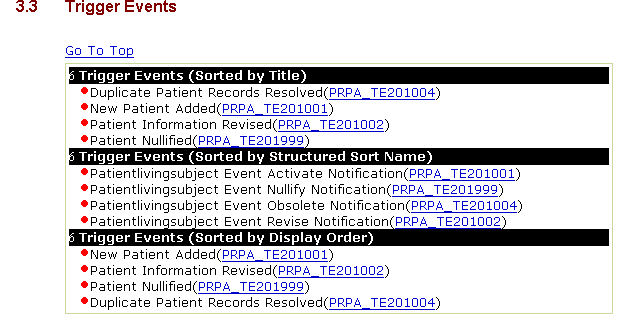
3.5
Domain Message Information Models
The Domain Message Information Model (D-MIM) is a subset of the RIM that includes a fully expanded set of class clones, attributes and relationships that are used to create messages for any particular domain. For example, the set of classes that are used by the Medical Records/Structured Documents domain is quite different from that used by the Patient Administration domain. The D-MIMs for these two domains, then, will be quite different, although both will be derived from the RIM.
Like the other models included in the V3 documents, the Domain Message Information Model is a diagram that shows the relationships between the classes but it uses diagramming conventions and notations that were developed by HL7 to represent the specific semantic constructs contained in the critical, "back-bone" classes of the RIM. Although D-MIMs and R-MIMs could be represented in UML notation, as the RIM is, the HL7 notation provides more details about the specific constraints and class clones being represented. The HL7 diagramming convention abbreviates some relationship conventions, enabling diagrams to be smaller and more concise and to convey more information visually. Understanding the diagramming conventions and notations is key to understanding how to read a D-MIM. The same diagramming conventions used for D-MIMs are also used for R-MIMs and CMETs (discussed in separate chapters of this guide). The rest of this chapter explains the conventions and notations used in the D-MIM diagram. Since a D-MIM is typically larger than a single, printable page, the figures in this chapter are sample portions of a D-MIM diagram that correspond to the convention being discussed.
3.5.1
Entry Points
Each D-MIM diagram will have at least one Entry Point. Entry Points designate the class(es) from which the messages begin for the particular domain. Since the D-MIM encompasses an entire domain, there may be several Entry Points, one for each R-MIM contained in the domain. Entry points are represented on the D-MIM diagram as clear boxes with thick black borders. A thick black arrow originates from the Entry Point box and points to a class which is considered the root, or focal class for one or more HMDs. Each Entry Point is named, carries the artifact ID of the R-MIM which originates from it, and contains a brief description. Provided below is a sample Entry Point box:
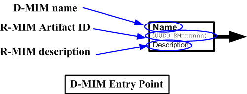
3.5.2
Classes and Colors
Like the RIM, the D-MIM's building blocks are the RIM classes and their attributes. However, in the D-MIM, the same class may appear multiple times in a diagram with different constraints (described below) or associations. These multiple instances of the same class are referred to as 'Clones'. For example, a D-MIM might have numerous clones of the Participation class, some for 'Author' participations, others for the 'Subject' participation, etc. Other classes may not appear at all. Only those classes, attributes and relationships that are required to build the messages for a particular domain are included in the D-MIM.
Classes in the D-MIM diagram are represented (much like they are in the RIM) by boxes. The class clone name (the name assigned to the particular instance of the class) is found in the upper left-hand side of the class box. Clone names are based on a formal algorithm discussed in the following sub-section. The color of the class box is significant as it identifies the RIM area to which the class belongs. The Act related classes are red, the Entity related classes are green and the Role related classes are yellow.
When the core RIM classes (Act, Entity and/or Role) are included in a D-MIM, the class_cd attribute of the core class as well as its value always appears as the first attribute in the clone. The class_cd attribute identifies the Vocabulary mnemonic or domain name associated with the class.
Non-core RIM classes included in the D_MIM will appear as dark blue boxes. Like the other classes, the clone name is contained in the top left of the box. The physical class name (as it appears in the RIM) displays in parentheses just below the clone name. The figure below shows sample classes as they might appear in a D-MIM:
3.5.3
Formal Names for Class Clones and Associations
HL7 allows copies of existing classes to be renamed in a particular context. This process is called "cloning" and the result is a class "clone". HL7 has defined a formal algorithm for naming the clones and associations that appear in a D-MIM or R-MIM. This approach assures that similar concepts will have common or similar names wherever they are used in HL7 specifications. Class clone names for Entity, Role and Act are based upon the class_cd value for the class. Additionally, for Act and Entity, the mood_cd or determiner_cd also affect the name. For example, an Act with class_cd of OBS (Observation) and mood_cd of PRMS (Promise) is named "ObservationPromise."
In a similar fashion, the type_cd is used to name clones of the Participation, Act_relationship and Role_link classes. Thus an Act_relationship with type_cd of COMP (has component) will be named "Component." The associations in the D-MIM are also named according to these algorithms, with the addition that the assigned names are appropriate to the direction of travel. Thus the relationship for an Entity that scopes the role of Patient will be named "healthCareProvider" whereas the traversal from the scoping Entity to the Patient Role will be named "patient."
Each associative class has four names (name into the class from the source direction;into the class from the target direction;out of the class from the source direction;out of the class from the target direction).Association names must be unique for the element where they originate, but do not have to be unique for the D-MIM or R-MIM.Where necessary, uniqueness is maintained by numbering subsequent association names i.e. "name" followed by "integer", "dataenterer02".
If a particular clone name should appear twice in a model, the second occurrence will be assigned the suffix "A" and so on. The technical committees have the privilege of replacing this suffix with a more meaningful term, and may also append additional suffix terms to any formal name in their model.
Technical committees are required to specify a "business name" for every Act, Role and Entity class. These names must be unique for a D-MIM or R-MIM.The business name is then what will be shown on R-MIM Visio diagrams and will also be used as the element name in an XML ITS.
3.5.4
Scoping Entities and Playing Roles: Dashed and Dotted Lines
If you look at the Role (yellow boxes) and Entity (green boxes) classes on a D-MIM diagram, you frequently see solid and dotted lines connecting them. One yellow Role class may be connected to up to two green Entity classes. These lines represent the relationships between the Role and Entity classes. One Entity is the player of the role (e.g., patient) while the other represents the Entity that scopes (recognizes or assigned) the role (e.g., a healthcare organization). The solid line for a role identifies playing Entity (e.g. the Person acting as Patient), while the dashed line represents the scoping Entity (e.g., the organization that assigned the role of Patient). Look at the relationships defined for the Patient, Person and Organization classes in the D-MIM below. The class_cd attribute in the yellow Patient role class identifies the role being played is PAT (patient). We arrive at Patient on the Entity side of the RIM by assigning PSN (person) as the class_cd in the Entity class. The id attribute in the Patient role will contain the patient number. The Entity recognizing the patient number for that Patient (and who the person is a patient of) is the Organization that scopes the role. We arrive at Organization on the Entity side of the RIM by entering ORG (Organization) as the class_cd in Entity.
The cardinality of the associations is shown adjacent to the lines. As shown below, Organization (green box) scopes zero or more Patients (i.e., the Organization assigns the role of Patient to zero or more Persons) while the Patient is scoped by one (and only one) Organization. On the playing end, the Patient is played by one Person (i.e., Patient is played by one Person) while the Person entity plays zero or more Patient (the person can play the role of patient zero or more times with respect to several provider organizations).
3.5.5
Relationship Classes: Arrowed Boxes
Five types of arrowed boxes may appear on a D-MIM. The salmon colored boxes represent Act_relationship classes, the blue arrowed boxes represent Participation classes and the yellow arrowed classes represent Role_link classes. In all of these relationships, there is a "source" for the relationship, and a "target." The tail of the arrow is anchored to the source class, while the head of the arrow points to the target class clone. Each of the directed relationships is described below:
- Act_relationship Classes - The Act_relationship class connects and therefore defines the relationship between two instances of the Act class.
- Participation Classes - Participation classes connect and therefore define the relationship between Act and Role classes. The type_cd in the Participation class identifies the way that the Entity playing the Role participates in a particular instance of an Act class.
Role_link Classes - Role_link classes do as their label suggests: they link two Role class instances, defining the relationship between the two.
The figure below shows the conventions used for Relationship, Participation and Role_link classes:
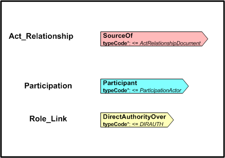
Non-core Class Associations - Non-core class associations, like the classes from which they originate, appear as dark blue arrows. The name of the association and the cardinalities appear adjacent to these arrows.
The figure below illustrates the conventions for non-core class associations.
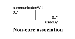
3.5.6
Recursive Relationships
Both Act Relationships and Role Links may be recursive. On the D-MIM diagrams, these recursive relationships are denoted as colored boxes (as noted in the Relationship section above) whose arrowed end is replaced by a notched out corner. The box's border is an arrowed line that points to the notched out corner of the box. The figure below illustrations the notations for both the recursive relationship classes:
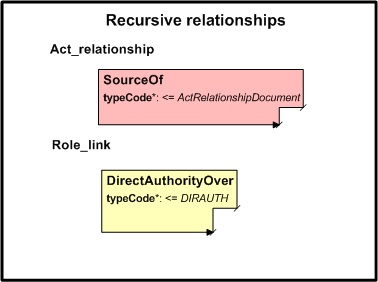
3.5.7
Inheritance
A recent addition to V3 has been the ability to control dynamically the standard inheritance rules which normally apply to UML and object modelling.
Context ControlCode
3.5.8
CMETs
CMETs (Common Message Element Types) are pre-defined components that are re-used for several R-MIMs and/or messages. A separate chapter in this guide provides additional details on CMETs. They are denoted on D-MIM diagrams as boxes with a dashed border. The color of the boxes is determined by the color of their base class (pink for Acts, yellow for Roles and green for Entities). The CMET boxes contain a name, the base class type, the artifact ID and the level of attribution. Each CMET has its own corresponding R-MIM diagram. These are defined separately and can be found in the CMET Section. The figure below shows the convention for denoting CMETs in the D-MIM diagram:

3.5.9
Choices
D-MIMs may also contain "Choice" boxes. These boxes are bordered by a dashed line and enclose two or more classes that are part of an inheritance hierarchy (e.g. two or more Roles, two or more Entities, etc.). It is important to note that any annotations or associations connected to the Choice box apply to all classes within it. Associations connected to a specific class within the choice box apply only to that class. In the figure below, the AR_for_choice Act_relationship applies to all classes within the Choice box. The AR_for_class Act_relationship, however, connects only to the Act2 class.
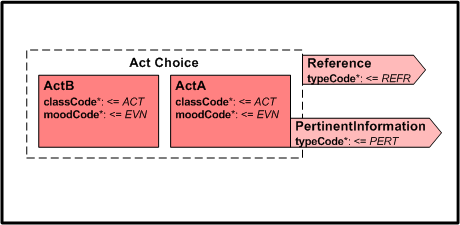
3.5.10
Attribute Conventions
A number of attribute conventions may appear in the D-MIM diagrams to convey information that would not otherwise be apparent. Typically, these conventions are used only if the default values are not used, although they may be used even if the default values are used. Conventions applied to a particular attribute appear beneath the particular attribute to which they apply and are slightly indented. The conventions that can be used are described below:
Mandatory inclusion - A bold attribute name indicates that the attribute is mandatory.
Domain - The vocabulary domain associated with a particular attribute instance is designated by the <= or = symbols. The domain specification must be either a domain name defined in the vocabulary tables, or a single code value from the appropriate domain.
Data type - Attribute data types may be specified by preceding them with a colon (":").
Vocabulary strength - Vocabulary strength may be denoted by the use of CWE (coded with extension [non-coded values allows where no appropriate code exists]) or CNE (coded, no extension [values must be coded]).
Cardinality - Attribute cardinalities are denoted within square brackets [ ]. These are expressed as N...N where N is a numeric or * for unlimited. For example (0...1).
Description - Brief descriptions of attributes may be included. Descriptions are enclosed within parentheses.
Alias - The alias convention denotes the original attribute name. This convention is used when the attribute shown on the D-MIM has been changed from the default RIM name. The default RIM attribute name is preceded by AKA: and enclosed within curly brackets. For example, {AKA: repeat_nbr} would denote that the attribute this appears with appears as repeat_nbr in the RIM.
3.5.11
Notes
Notes providing additional information about a particular class may appear in the D-MIM Diagram. Notes are depicted as clear, oblong boxes bordered in black with the top right corner folded down. An arrow originates from the Note box and points to the class being described. A sample note is depicted in the figure below.
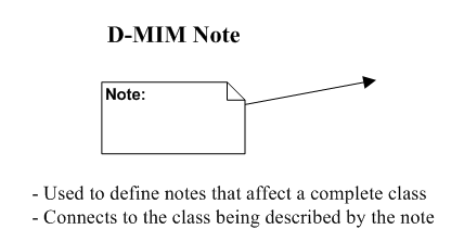
3.5.12
Constraints
Constraints can be placed on a class or an attribute. An example of a constraint placed on a class might be something such as "Either nm or id must be specified." Constraints are denoted by a light blue shaded box that points to the class or attribute that is being constrained. If the constraint applies only to a particular attribute, the constraint box will contain the name of the attribute in the upper left corner. If this area is blank, the constraint applies to the entire class to which the constraining box points. The constraint box holds a formal constraint expression within curly brackets and the textual description of the constraint appears after the closing curly bracket.

3.5.13
Annotations
In the standards themselves, the D-MIM diagrams are followed by Annotations. The annotations can be of two types, either a development note or a walkthrough note. Development notes explain why things were modeled as they were. Walkthrough notes are intended to help the reader more thoroughly understand the D-MIM itself.
3.6
Refined Message Information Models
Refined Message Information Models (R-MIMs) are used to express the information content for one or more HMDs that originate from the root class identified by the Entry Point in the R-MIM. Each R-MIM is a subset of the D-MIM and contains only those classes, attributes and associations required to compose the set of messages derived from the HMDs that originate from the R-MIM root class. Classes, attributes and associations that are not required for those HMDs are eliminated and the generalization hierarchies are also collapsed.
Each CMET has an associated R-MIM and these can be seen in the CMET chapter which defines all currently used CMETs
The R-MIM diagrams use the same conventions and notions that are used in the D-MIM diagrams. Please refer to that chapter for specific information about how to read these diagrams. There is however an additional level of documentation available for R-MIMs. An R-MIM now has clickable hyperlinks on each class in the R-MIM which link to a table view. This provides an easy way to reference any additional documentation which has been provided in the table view.
3.7
Hierarchical Message Descriptions and Message Types
This chapter describes the Hierarchical Message Descriptions (HMD) and their resulting message types, which define the message payload.
Some questions that are frequently asked are:
"Why do we need to create an HMD? If we already know the sender, the
receiver, the trigger event and the classes, why not just send the
data?" There are several important answers to this question.
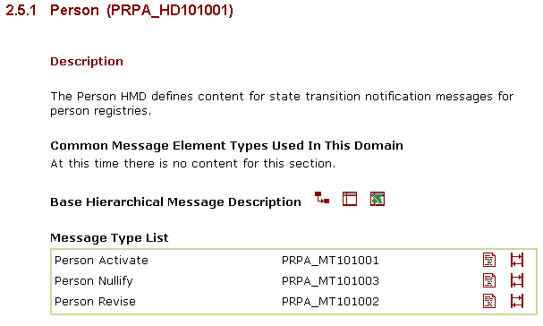
The information model contains a group of classes that frequently are interconnected in more than one way. For example, there may be associations that lead from Patient to Person directly (this is the person who is the patient) and indirectly (this is the person who is the next of kin of the patient, or this is the person who is the primary physician of the patient).
The communicating systems must be able to determine which of the objects derived from these classes contain the data to be sent. Furthermore, they must be able to navigate to the related objects through the associations that are defined for the classes.
The same attributes may not be appropriate for different objects. Although both the patient and the physician associated with a clinical order are people, it is unlikely that we will send the physician's religion, date of birth, or sex each time we process an order for the patient.
The communicating systems must be aware which of the objects will be sent.
Finally, to send data over the wire, the computer must organize it sequentially. There are many different ways to organize the data from a group of objects interconnected by their associations. If the sender and the receiver do not agree exactly on that order, the communication is frustrated. If the sender transmits information about the attending physician before that of the primary care physician, and the receiver is expecting the opposite order, there will be a problem.
The communicating systems must know the exact sequence in which information will be sent.
The HMD and its corresponding message types specify these choices. In simplest terms, an HMD is a tabular representation of the sequence of elements (i.e., classes, attributes and associations) represented in an R-MIM and that define the message without reference to the implementation technology. The HMD defines a single base message structure - the "common" message type. This base message structure is never sent and thus has no corresponding trigger event. It is the template from which the other specific and corresponding message types are drawn. The RoseTree tool therefore requires that a specific HMD is identified in order that an appropriate HMD can be output and an XML schema produced. The HMD and its contained message types may be downloaded as an Excel spreadsheet and a sample XML Example is also available.
A message type represents a unique set of constraints applied against the common message. Successive ballots may introduce additional message types for HMDs that have been defined in previous releases. The message types will be diffierentiated in terms of the particular trigger event that applies.
3.7.1
Use of mandatory and conformance indicators
The following table shows how mandatory and conformance indicators are used to refine use of an HMD
| Constraint | Description |
|---|---|
| Cardinality | This specifies the minimum and maximum number of occurrences (repeats) of the field/association. For example, 1..* implies the minimum number of occurrences (repeats) is 1 whereas the maximum number of occurrences (repeats) is unlimited. |
| Mandatory | Valid values are M (mandatory) or Blank (not mandatory). M (mandatory) means that the field/association must be present in the message, otherwise the message is invalid and is non-conformant. For Mandatory fields, HL7 sets the minimum cardinality to 1 (a value must be present). Blank (not mandatory) means that the field/assocation does not need to be present in the message. |
| Conformance | Valid values are R (required), NP (not permitted), and Blank (optional). R (required) means that the sending application must support this field/association. If the data is available, then the field/association is included in the message. If the minimum cardinality is 0 and the data is not available, the field/assocation may be omitted from the message and still be conformant. If the minimum cardinality is 1 and the data is not available, a NullFlavor is required (see below). NP (not permitted) means that the field/assocation is not included in the message schema and never included in a message instance. Blank (optional) means that the field/assocation may/may not be sent and support for this field/association is not required of sending applications. Conformance for this element is to be negotiated on a site-specific basis. |
| NullFlavor | For required fields/associations with a minimum cardinality of 1, a NullFlavor must be sent for fields/associations that are not available to a sending application. Sample Nullflavors are "no information", "unknown", "masked" (for privacy applications), "not asked" and "asked, but unknown" (patient asked but did not know valid answer). |
| Cardinality | Mandatory | Conformance | NullFlavor Required? | Explanation of Rules |
| 0.., 1.. | No | The field/association may or may not be present in a message. Conformance for this element is to be negotiated on a site-specific basis | ||
| 0.., 1.. | NP | Not allowed | The field/assocation is not present in the schema and cannot be included in a message instance. | |
| 0.. | R | No | Support for the field/association is required in a sending application. The field/assocation may or may not be present in a message. | |
| 1.. | R | Yes | Support for the field/association is required in a sending application. The field/assocation must be present in a message, but may not be valued. If the field/assocation is not valued, a NullFlavor must be specified. | |
| 1.. | M | R | Not Allowed | Support for the field/assocation is required in a sending application. NullFlavor may not be specifed. The field/assocation must be present and valued in a message. |
The common message type and the specific message types are presented in Excel and table view, as well as an XML schema.
3.7.2
Message Type Column Descriptions- Excel View

| Column | Description |
|---|---|
| No | Row number. Each row is sequentially numbered and identifies the order in which the data were serialized from the R-MIM. |
| Element Name | The name of the element as it appears in the R-MIM. This may or may not be the same as the value in Property. This value will be different when a class, association or role is cloned and renamed in the process of creating the R-MIM. |
| (row type) | Each row represents either a class, an association or an attribute from the R-MIM. Class rows have their name displayed in bold; associations have their name in italics; and attributes have their names in plain font. |
| Card | Cardinality. This specifies the minimum and maximum number of occurrences of the message element. |
| Mand | Mandatory. Valid values are M (Mandatory) or Blank. An M in the field requires that some data be sent for this element. If the data is not known, a value of unknown, not given, etc. must be sent. An M in this column (for Mandatory) differs from a 1 in the Cardinality column in that an M indicates that the message cannot be validly parsed without a value in this field or without defining a default. If no default is provided, you either do not send a message or must send a value. An M in this column also differs from an R in the Conformance column (explained below). |
| Conf | Conformance. Valid values are R (required), NP (not permitted), and Blank (not required). A value of R (required) means that the message elements must appear every time the message is used for an Interaction. If the data is available, the element must carry the data. If the data is not available, a blank may be sent. NP (not permitted) means that the message element is never sent for this message type. Blank means that conformance for this element is to be negotiated on a site-specific basis. |
| RIM Source | Identifies the class from which the attribute or association originates. |
| Of Message Element Type | This column identifies the data type of attributes or class name of associations. |
| SRC | Message Element Type Source. Valid values are D (data type), N (new, being defined starting at this row), U (use, meaning that an element, but not its value, from a previous row in the HMD is being reused), C (CMET), I (Instance, refers to the reuse of a particular element and its value as defined previously in the HMD), and R (recursive, into itself). |
| Domain | Vocabulary Domain Specification. Clicking on this link will take you to the Domain Specification for this element. |
| CS | Coding Strength. Valid values are CWE (coded with extensions, meaning that the code set can be expanded to meet local implementation needs) and CNE (coded no extensions, meaning that the code set cannot be expanded). |
| Abstract | Is a boolean assigned to classes or associations in a gen-spec hierarchy, which becomes a choice in an HMD. If the value is true, then this type may not appear in message instances. |
| Nt | Note. If one is provided, this is simply a free text note provided by the committee. |
3.7.3
Message Types - Table View

The table view of the common message and individual message types is an expression of the message type definition condensed enough in a size to fit on a printed page.
3.7.4
Schema View

Provided for the individual message types, this is a link to the schema used to validate all XML messages that conform to the particular message type.
3.7.5
Example

Provided only for the Base HMD this is an XML message rendered from the schema and message type definition.
3.8
Interactions
Interactions are at the heart of messaging. The formal definition of an interaction is:
A unique association between a specific message type (information transfer), a particular trigger event that initiates or "triggers" the transfer, and the application roles that send and receive the message type. It is a unique, one-way transfer of information.
A single Interaction explicitly answers the questions:
Which type of system component sends a particular type of message;
To what type of receiving system component the message type is sent;
How a system knows when to send a particular type of message;
What the particular message type is;
Interactions are also discussed in the Storyboard chapter. The graphic that typically appears with the storyboard is an Interaction Diagram. As mentioned in the Storyboard chapter, the boxes at the top of the Interaction diagram and the associated vertical lines represent the application roles, the types(s) of system components that send and receive a particular message. The horizontal lines on the Interaction Diagram are the interactions themselves, thus answering the first two questions above.
As the list above indicates, each interaction is related to a sending role, a receiving role (both of which were identified on the Interaction Diagram), a trigger event, and a message type. In the Version 3 specifications, the Interactions are presented with a name, the artifact ID, and a table that lists the sending role, the receiving role, the trigger event, the message type, the Event type and the Wrapper type.
The Event type is the Trigger Event type. Valid values are interaction-based, state-transition based, user-based or unspecified. Refer to the Trigger Event section in this part of the V3 Guide for additional information on the Trigger Event type.
The Wrapper type,where specified, refers to the Control event wrapper. The Control Act wrapper is an additional optional wrapper which contains domain specific administrative information related to an interaction which triggered this message (i.e. the message to which a Control Act wrapper is being specified to be added). This type of wrapper does not appear with HL7 messages where there is no additional context that is needed to be exchanged dynamically, or with HL7 messages that are carrying commands to coordinate the operation of message handling services. Two areas addressed in the current Control Act wrapper definition are:
- Query
- Registry (such as updating a Master-Patient Index)
The figure below depicts an Interaction as it appears in the Version 3 Specification:
Each entry in the table is a hyperlink that takes you back to the particular artifact in question.
3.9
V3 message wrappers and Infrastructure
HL7 V3 provides a substantial level of functionality in the provision of envelopes to support the transport of HL7 messages from sender to receiver. HL7 calls these wrappers. Inside the wrapper is Domain Content. Wrappers are all defined in the same way as for message content, by defining object classes and related relationships. These specifications can then be used to generate an XML schema, or other ITS-defined syntax to go on the wire. HL7 tools are being designed to automatically pick up the appropriate type of wrapper as part o the process of message generation. The infrastructure ballot is organised as four separate domains. The four domains are:-
- Transmission Infrastructure
- Message Control Act
- Query Infrastructure
- Master File Infrastructure
This allows a common approach to defining these standards with how message content is defined in the various application domains. Making use of the normal message definition structure is particularly useful however in being able to define (application) roles and interactions, which are particularly applicable to more complex wrapper functionality. HL7 prefers to define such a rich set of functions within the HL7 standards scope because there is no de facto way of providing these functions in a single standard that could be adopted. HL7 is now defining transport specifications which indicate how underlying transports such as eBXML or Web Services can be used to transport HL7 messages.
3.9
HL7 Transmission wrapper (ballot: Infrastructure Domain)
The HL7 Transmission wrapper is required for all V3 messages. It contains a large number of optional fields so the message overhead will vary from one context to another. Technical committees or realms who perform refinement on the transmission wrapper need to ensure that tooling is in place to pick up their modified wrapper rather than just the default. For instance when using an XML ITS, the final output needs to be an XML schema comprising message content, the transmission wrapper, and, optionally, a Control Act wrapper.
Associated with use of the wrapper are a number of services that are available as needed:-
Three messages are defined to support these functions and each one has an R-MIM and HMD. The two acknowledgement message types with very different roles. One is to support reliable delivery at the network level. Increasingly however HL7 V3 messaging will make use of external transport services that do not require use of an HL7-defined network acknowledgement. The same is true of the optional message sequence number protocol. It is an essential component of supporting reliable delivery at the network level, but again not required if an external reliable transport is used such as the three HL7 transport profiles now all at DSTU. The application acknowledgement is very different. It is triggered only by inclusion in an Interaction and with a defined trigger event. It may carry domain content and therefore combine the general functionality of an application acknowledgement, with the specific response defined by the domain for this Interaction.
All the message structures in the Transmission Domain have mandatory attributes which define the sending and receiving systems in a message transmission (DeviceID). Additional information about the Sender and Receiver in other classes, but the use of a mandatory attribute ensures that a transport protocol such as the ebXML DSTU can define an attribute copy procedure which will allow the values in Device ID to be also held in the ebXML wrappers. A later paragraph in this Section summarises the commonalities and differences between the three transport DSTU specifications.
The Transmission wrapper offers an additional set of functions to support polling. These functions are included for compatibility with some early V2 use. Polling is probably a matter of limited interest to implementors, other than those with particular legacy problems.
- Send Poll Response w/ Message
- Send Accept Ack/Poll Next Msg
3.9
Control Act wrapper(ballot: Infrastructure Domain)
Additional richness in functionality is provided by the Control Act wrapper,which is used when information about the interaction which has triggered a message needs to be communicated within that message to the receiver. In some cases, these interactions will have been fully defined by the interaction model and therefore there is no need for such information to be included inthe message. Two particular areas of application are query sessions and registry interactions (such as Master Person Index). Technical committees will individually decide when a Control Act wrapper needs to be specified for a particular message. A generic wrapper definition is supplied as part of the Infrastructure ballot. Technical Committees may carry out refinement on the wrapper to meet their own needs. Future tooling will need to be able incorporate domain-specific wrappers when necessary. This is outside the capability of the current tooling. These wrappers are described in the HL7 ballot in three main groupings, described as separate domains:-
- Message Control Act Infrastructure (MCAI) -defining the Control Act itself.
- Query Infrastructure (QUQI) -which describes how to use the wrapper to support queries
- Master File Infrastructure (MFMI)
3.9.1
Message Control Act Infrastructure
MCAI defines the detail of the Control Act. Key uses are for Query and Master File applications, these are summarised in the next two paragraphs.
3.9.2
Query Infrastructure
The objective is to set up a general structure for queries and their response. Three messages are defined along with appropriate roles and interactions.
- Query General Activate Query Continue
- Query General Response
- Query by Parameter specification
3.9.3
Master File Infrastructure
A typical application is an MPI Master Patient Index. Again, the intention is to define a general set of messages that can be used to maintain any type of patient or professional database, or similar. In these functional areas, there are no specific messages against the message functionality required. The Control Act is used to define what is needed, together with a set of standard trigger events, and an appropriate state diagram.
A
References
- Message Development Framework
- HL7 Version 3 Standard: Message Development Framework, HL7 Version 3 Taskforce
- HL7 Version 3 Standard: Administrative Management
- HL7 Version 3 Standard: Administrative Management, HL7 Version 3 Taskforce
- HL7 Version 3 Standard: Infrastructure Management
- HL7 Version 3 Standard: Infrastructure Management, HL7 Version 3 Taskforce
- HL7 Version 3 Standard: Health and Clinical Management
- HL7 Version 3 Standard: Health and Clinical Management, HL7 Version 3 Taskforce
- HL7 Version 3 Standard: Vocabulary
- HL7 Version 3 Standard: Vocabulary, HL7 Version 3 Taskforce
- HL7 Version 3 Statement of Principles
- HL7 Version 3 Statement of Principles, HL7 Version 3 Taskforce
- Method for the Development of Healthcare Messages
- Method for the Development of Healthcare Messages, CEN TC 251
- Object Oriented Software Engineering
- Object Oriented Software Engineering, Ivar Jacobson, et al.
- Object Oriented Analysis
- Object Oriented Analysis, Peter Coad & Ed Yourdon
- Open EDI Reference Model
- Open EDI Reference Model, ISO/IEC CD 14662
- Unified Method, Version 0.8
- Unified Method, Version 0.8, Grady Booch & James Rumbaugh
- UML Distilled
- UML Distilled, Martin Fowler with Kendall Scott
Endnotes
- [source] In other models, the lower case letters "n" or "m" are sometimes used, indicating integer variables. This notation is not defined in the UML Notation Guide. The problem with using letters instead of the asterisk is that if the same letter is used more than once, it may be misunderstood to represent the same integer number everywhere. Furthermore, an "n" indicates some boundary specified elsewhere, while the asterisk ("*") indicates unbounded multiplicity, without the notion of any dependency between such multiplicities.